A gear variable speed disc water pump

A gear and disc type technology, applied in the field of gear speed disc type water pump, can solve the problems of poor practicability and functionality of the water pump, inconvenient adjustment of impeller torque, long pump length, etc., to improve the use environment, improve torque, reduce effect of stress

Active Publication Date: 2022-01-14
ANHUI JINWAN PUMP TECH CO LTD
View PDF14 Cites 0 Cited by
  • Summary
  • Abstract
  • Description
  • Claims
  • Application Information

AI Technical Summary

Problems solved by technology

[0005] In order to overcome the above-mentioned existing water pumps, most of them use ordinary motors to act as driving components, resulting in longer lengths of the water pumps, which have certain requirements on the installation site and site. There are certain work requirements, and the practicability and functionality of the existing water pumps are poor, and it is inconvenient to adjust according to the technical problems during use. The purpose of the present invention is to provide a gear variable speed disc water pump

Method used


Image

  • A gear variable speed disc water pump
  • A gear variable speed disc water pump
  • A gear variable speed disc water pump

Examples


Embodiment 1

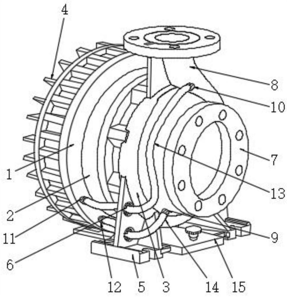
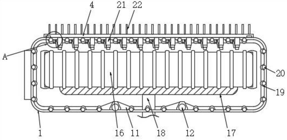
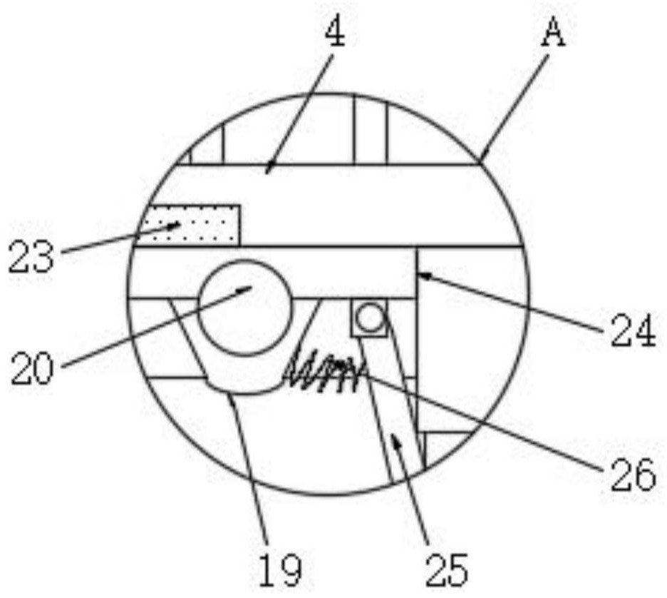
[0053] Insert the embedded plate 21 of the cooling plate 4 into the slot 24 of the disc motor 1. When the embedded plate 21 is embedded, it will push away the sealing plate 25 by compressing the first return spring 26. At the same time, the cooling plate 4 passes through the permanent magnet 23 Adsorption connection with the rear wall of the disc motor 1, the two ends of the first connecting pipe 13 are screwed to the outside of the second outlet pipe 11 and the first water inlet pipe 10, and the two ends of the second connecting pipe 14 are threaded to the second The outside of the two water inlet pipes 12 and the first water outlet pipe 9, when the first connecting pipe 13 and the second connecting pipe 14 are installed, pass through two groups of holders 6 respectively, when passing through two groups of holders 6 , change the length of the telescopic column 63 by compressing the elastic filling particles 64, expand the chuck 61 and the pad 62, and release the telescopic col...

Embodiment 2

[0057] The first water outlet pipe 9, the first water inlet pipe 10, the second water outlet pipe 11 and the second water inlet pipe 12 are tightly sealed with a sealing cover, and the sealing plate 25 is closely attached to the slot 24 driven by the first return spring 26 One side of the disc motor 1 is separated and sealed from the outside;

[0058] Pull out the block 27 of the support plate 15 from the slots 51 of the two sets of support plates 5, store the support plate 15, and keep the rotating wheel 31 from the prism block 30 up and down;

[0059] Start the disc motor 1, the connecting shaft 18 in the disc motor 1 drives the gear box 2 to work, after the gear box 2 works, it drives the impeller inside the impeller box 3 to rotate, pumping water from the water inlet valve 7 to the water outlet valve 8. Adjust the speed change member in the gear box 2, change the speed change of the gear box 2, and finally change the rotation speed of the impeller in the impeller box 3.


PUM


Abstract

The invention discloses a gear-variable disc water pump, which relates to the technical field of water pumps and comprises a disc motor and an impeller box. A gear box is fixedly connected between the disc motor and the impeller box. The connecting shaft of the disc motor One end is fixedly connected to the input end of the gear box, the output end of the gear box runs through the impeller box, and the output end of the gear box box is fixedly connected to the impeller, the two sides of the impeller box are welded with support plates, one side Two sets of holders are fixedly connected to the inside of the support plate, and a cooling plate is embedded and connected to the rear surface of the disc motor. The water pump in the present invention uses a disc motor as the driving component, thereby reducing the overall length of the water pump and reducing the demand for the installation site of the water pump. At the same time, the present invention adds a gear box between the driving component and the impeller of the existing water pump, which can Changing the speed ratio between the disc motor and the impeller can facilitate the staff to adjust the speed of the impeller.

Description

technical field [0001] The invention relates to the technical field of water pumps, in particular to a gear variable speed disc water pump. Background technique [0002] Centrifugal water pump is composed of pump casing, impeller, pump shaft, pump frame, etc. Before starting, the pump should be filled with water. After starting, the motor drives the impeller to rotate, and the rotating impeller drives the water in the pump to rotate at high speed, and the water makes centrifugal motion. , thrown out and pressed into the outlet pipe, after the water is thrown out, the pressure near the impeller decreases, forming a low pressure zone near the shaft. [0003] A Chinese patent discloses a variable frequency speed regulating disc motor and a vacuum pump (publication number: CN103457366B). This patent adopts a sinusoidal winding in a double-layer type. The electrodes are connected in order to make the magnetic field distribution more uniform, the waveform is close to a sine wave,...

Claims


Application Information

Patent Timeline
Patent Type & Authority Patents(China)
IPC IPC(8): F04D13/06F04D29/58F04D29/00F04D15/00H02K5/00H02K5/18H02K7/116H02K9/193
CPCF04D13/0666F04D29/5806F04D29/586F04D29/007H02K7/116H02K9/193H02K5/18H02K5/00F04D15/0066
Inventor 侯迪迪张利利韩雨晴王露颖倪松翔余庆余安琪韩昌宇余雷
Owner ANHUI JINWAN PUMP TECH CO LTD
Why Eureka
Try Eureka