Desulfurization liquid regeneration tank capable of realizing bottom horizontal jet flow.

A desulfurization liquid and regeneration tank technology, which is applied in the separation of dispersed particles, chemical instruments and methods, separation methods, etc., can solve the problems of no desulfurization liquid mixing and stirring, large flow dead zone at the bottom of the tank, and sulfur easily deposited on the bottom of the tank, etc. , to further inhibit the shear diffusion, improve the oxidation rate, and improve the efficiency of oxidation regeneration.

Pending Publication Date: 2020-12-29
ACRE COKING & REFRACTORY ENG CONSULTING CORP DALIAN MCC
View PDF1 Cites 3 Cited by
  • Summary
  • Abstract
  • Description
  • Claims
  • Application Information

AI Technical Summary

Problems solved by technology

[0005] At present, the injectors in the desulfurization liquid regeneration tank are all vertically arranged and arranged in a ring, and the gas-liquid mixing outlet faces the bottom of the regeneration tank. After the desulfurization liquid mixed with air enters the regeneration tank at a certain speed, it is directly flushed To the bottom of the regeneration tank, the desulfurization liquid is not fully mixed and stirred, the energy loss is large, the flow dead zone in the bottom area of ​​the tank is large, and sulfur is easily deposited at the bottom of the tank, resulting in low regeneration efficiency

Method used


Image

  • Desulfurization liquid regeneration tank capable of realizing bottom horizontal jet flow.
  • Desulfurization liquid regeneration tank capable of realizing bottom horizontal jet flow.
  • Desulfurization liquid regeneration tank capable of realizing bottom horizontal jet flow.

Examples


Embodiment Construction

[0025] The specific embodiment of the present invention will be further described below in conjunction with accompanying drawing:

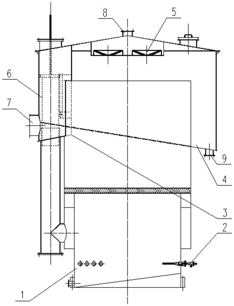
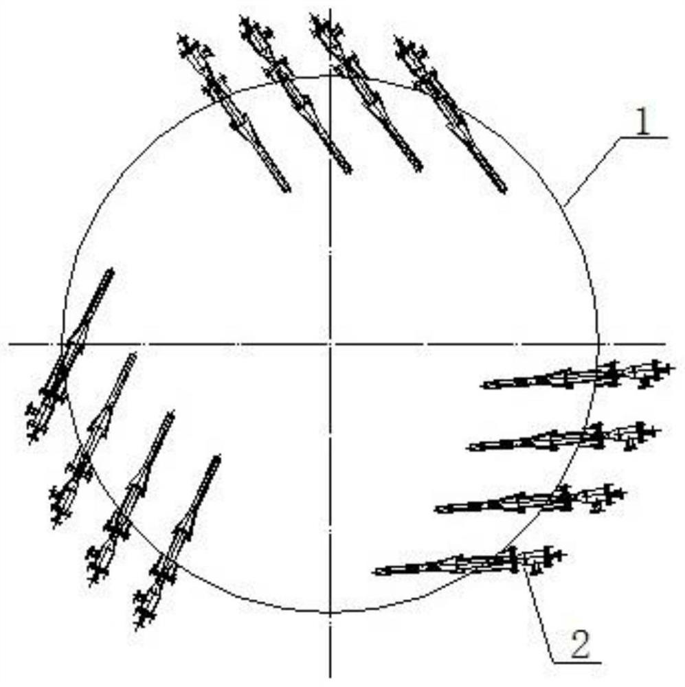
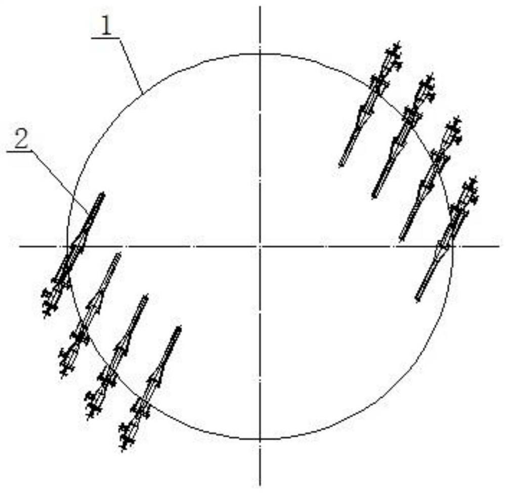
[0026] Such as figure 1 As shown, a desulfurization liquid regeneration tank with bottom horizontal jet flow according to the present invention comprises a desulfurization liquid tank 1, a foam tank 4 and a liquid level regulator 6; the foam tank 4 is arranged on the top of the desulfurization liquid tank 1, and the foam tank The diameter of 4 is greater than the diameter of desulfurization liquid tank 1, and an annular sulfur foam storage tank is formed between the two, and a sulfur foam outlet 9 is arranged at the bottom of the sulfur foam storage tank; side, the bottom of the liquid level regulator 6 communicates with the lower part of the desulfurization liquid tank 1, and the upper part of the liquid level regulator 6 passes through the foam tank 4; A group of jet ejectors, each group of jet ejectors is composed of a plurality of jet ejector...


PUM


Abstract

The invention relates to a desulfurization liquid regeneration tank capable of realizing bottom horizontal jet flow. The desulfurization liquid regeneration tank comprises a desulfurization liquid tank, a foam tank and a liquid level regulator; the desulfurization liquid regeneration tank further comprises a plurality of groups of jet ejectors arranged at the bottom of the desulfurization liquid tank, each group of jet ejectors consists of a plurality of jet ejectors arranged in parallel, and each group of jet ejectors are horizontally arranged along the tangential direction of the desulfurization liquid tank; and a liquid phase inlet of the jet ejector is connected with a desulfurization liquid pipeline, and a gas-liquid mixing outlet faces the interior of the desulfurization liquid tank.A plurality of groups of jet ejectors which are horizontally arranged are arranged at the bottom of the desulfurization liquid regeneration tank, and desulfurization liquid and air are fully mixed inthe jet ejectors, so that preliminary oxidation regeneration is realized; and after a gas-liquid mixture sprayed out from the jet ejector enters the desulfurization liquid regeneration tank, the desulfurization liquid is mixed and stirred through the jet shearing effect, so that further oxidation regeneration of the desulfurization liquid is achieved, the oxidation rate is increased, and sulfur can be prevented from being deposited after being focused.

Description

technical field [0001] The invention relates to the technical field of desulfurization liquid regeneration, in particular to a bottom horizontal jet flow desulfurization liquid regeneration tank. Background technique [0002] Wet oxidation desulfurization technology is one of the desulfurization methods widely used in the domestic chemical industry. It uses dilute alkali to absorb H in the gas phase. 2 S, in absorbing H 2 Due to the action of the oxidation catalyst in the liquid phase of S, the H 2 S is oxidized to elemental sulfur and separated for recovery. The oxidation catalyst is the oxygen carrier. The oxygen carrier in the oxidized state oxidizes the absorbed H2S in the solution into elemental sulfur, and at the same time becomes a reduced oxygen carrier by itself. Through regeneration, the reduced oxygen carrier is absorbed by the oxygen in the air. Converted to an oxygen carrier in an oxidized state, this cycle changes repeatedly to achieve the goal of removing H...

Claims


Application Information

Patent Timeline
Patent Type & Authority Applications(China)
IPC IPC(8): B01D53/52B01D53/78B01D53/96B01D45/12
CPCB01D45/12B01D53/52B01D53/78B01D53/96
Inventor 谭瑞春段有龙
Owner ACRE COKING & REFRACTORY ENG CONSULTING CORP DALIAN MCC
Why Eureka
Try Eureka