Full-angle mode circuit gain error self-compensation system of micro-electro-mechanical gyroscope

A micro-electromechanical gyro and gain error technology, applied in the direction of physical parameter compensation/prevention, gyro effect for speed measurement, gyroscope/steering sensing equipment, etc., can solve the problem of reducing the accuracy and accuracy of angle detection and increasing the residual error of angle output , circuit gain error and other issues, to achieve the effect of improving angle detection accuracy and control accuracy, good circuit gain error compensation, and fast response speed

Active Publication Date: 2020-12-29
NANJING UNIV OF SCI & TECH
View PDF9 Cites 13 Cited by
  • Summary
  • Abstract
  • Description
  • Claims
  • Application Information

AI Technical Summary

Problems solved by technology

However, in most applications, the Q values ​​(quality factors) of the two modes of MEMS gyroscopes are different, so the actual gains of the x and y axes are also different. Gain error of the circuit
The angle calculation in the full-angle mode will introduce this error, resulting in a larger residual error of the angle output, which reduces the accuracy and accuracy of angle detection

Method used


Image

  • Full-angle mode circuit gain error self-compensation system of micro-electro-mechanical gyroscope
  • Full-angle mode circuit gain error self-compensation system of micro-electro-mechanical gyroscope
  • Full-angle mode circuit gain error self-compensation system of micro-electro-mechanical gyroscope

Examples


Embodiment Construction

[0023] The present invention will be further introduced below in conjunction with the accompanying drawings and specific embodiments.

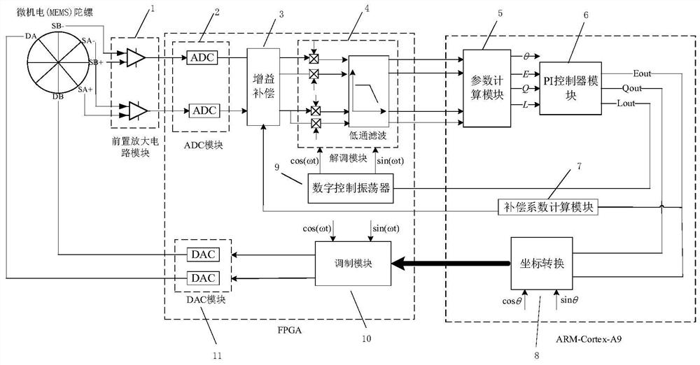
[0024] The micro-electromechanical gyroscope applicable to the system has two electrode axes, namely the x-axis and the y-axis, the x-axis includes a drive electrode DB, and 2 differential detection electrodes (SB-, SB+); the y-axis includes a drive electrode DA , 2 differential detection electrodes (SA-, SA+). Since the MEMS multi-ring gyroscope has structural asymmetry and damping and stiffness asymmetry caused by processing errors, the rotation angle θ of the MEMS multi-ring gyroscope is the decay time constant caused by the actual rotation angle and time delay. It is the result of the combination of factors such as the mismatch error, the axial frequency difference Δω of the two electrodes, and the phase mismatch error existing in the actual loop.

[0025] A full-angle measurement and control circuit method of a micro-electromechanical mu...


PUM


Abstract

The invention discloses a full-angle mode circuit gain error self-compensation system of a micro-electro-mechanical system gyroscope. The full-angle mode circuit gain error self-compensation system comprises a gyroscope pre-amplification circuit, an ADC module, a gain compensation module, a demodulation module, a parameter calculation module, a PI controller module, a coordinate conversion module,a compensation coefficient calculation module, a modulation module and a DAC module. The pre-amplification circuit module is connected to a detection electrode of the micro-electro-mechanical multi-ring gyroscope, the ADC module is connected to the pre-amplification circuit, the gain compensation module is connected to the ADC module, the demodulation module is connected to the gain compensationmodule, the PI controller module is connected to the parameter calculation module, the compensation coefficient calculation module is connected to the PI controller module, the coordinate conversion module is connected to the PI controller module, the modulation module is connected to the coordinate conversion module, the DAC module is connected to the modulation module, and the digital control oscillator module is connected to a PI controller. According to the system, real-time circuit gain error self-compensation in a full-angle mode of the micro-electro-mechanical gyroscope can be realized.

Description

technical field [0001] The invention belongs to the field of microelectromechanical systems, in particular to a full-angle mode circuit gain error self-compensation system for microelectromechanical gyroscopes. Background technique [0002] As a new type of gyroscope, micro-electromechanical (MEMS) gyroscope uses single crystal silicon as the main processing material. Compared with the traditional mechanical structure gyroscope, it has the advantages of small energy dissipation, high mechanical sensitivity, Concentrated mass, low mechanical noise and so on. Because of the above advantages, micro-electromechanical (MEMS) gyroscopes occupy an important position in the field of gyroscopes. [0003] In practical applications, micro-electromechanical (MEMS) gyroscopes can work in full-angle mode. Although the structure of the full-angle measurement and control circuit system is complex, it can directly output the rotation angle of the gyroscope. However, in most applications, t...

Claims


Application Information

Patent Timeline
Patent Type & Authority Applications(China)
IPC IPC(8): G01C19/56G01C19/5776H03M1/06
CPCG01C19/56G01C19/5776H03M1/06
Inventor 樊琦周怡苏岩
Owner NANJING UNIV OF SCI & TECH
Why Eureka
Try Eureka