Multi-frequency-point radio frequency impedance and current testing system

A technology of current testing and radio frequency current, which is applied in the directions of only measuring current, measuring current/voltage, measuring resistance/reactance/impedance, etc. It can solve the problems of inaccurate testing, irreversible compression, etc., and achieve convenient nonlinearity and electromagnetic compatibility, etc. , good transmission performance, and the effect of optimizing test performance

Active Publication Date: 2020-12-29
海宁利伊电子科技有限公司
View PDF5 Cites 2 Cited by
  • Summary
  • Abstract
  • Description
  • Claims
  • Application Information

AI Technical Summary

Problems solved by technology

[0004] Aiming at the deficiencies of the existing radio frequency test system, the purpose of the present invention is to provide a multi-frequency point radio frequency impedance fixture and radio frequency current probe system to solve the actual test, while obtaining parameters such as current and impedance of the test piece. , which improves test performance
[0006] Aiming at the deficiencie

Method used


Image

  • Multi-frequency-point radio frequency impedance and current testing system
  • Multi-frequency-point radio frequency impedance and current testing system
  • Multi-frequency-point radio frequency impedance and current testing system

Examples


Embodiment Construction

[0044] In order to enable those skilled in the art to better understand the solution of the present invention, and to make the above-mentioned purpose, features and advantages of the present invention clearer and easier to understand, the present invention will be further described in detail below in conjunction with examples.

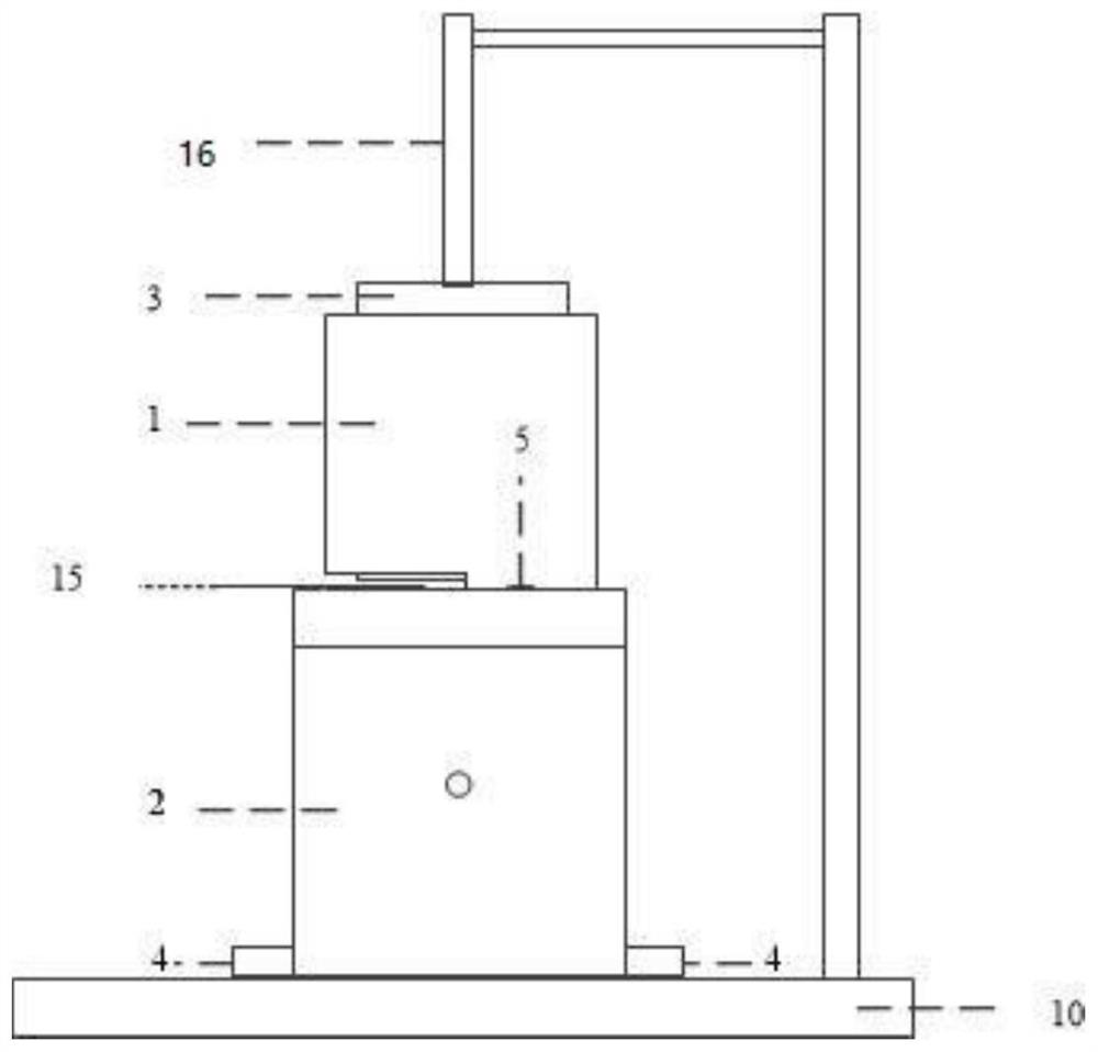
[0045] The specific implementation of the system is as figure 1 As shown, it includes a radio frequency multi-frequency point test fixture, a radio frequency current probe and test instruments; the specific test instruments are vector network analyzers and spectrum analyzers. The test system tests the device under test for gap shielding materials such as foam and conductive cloth.

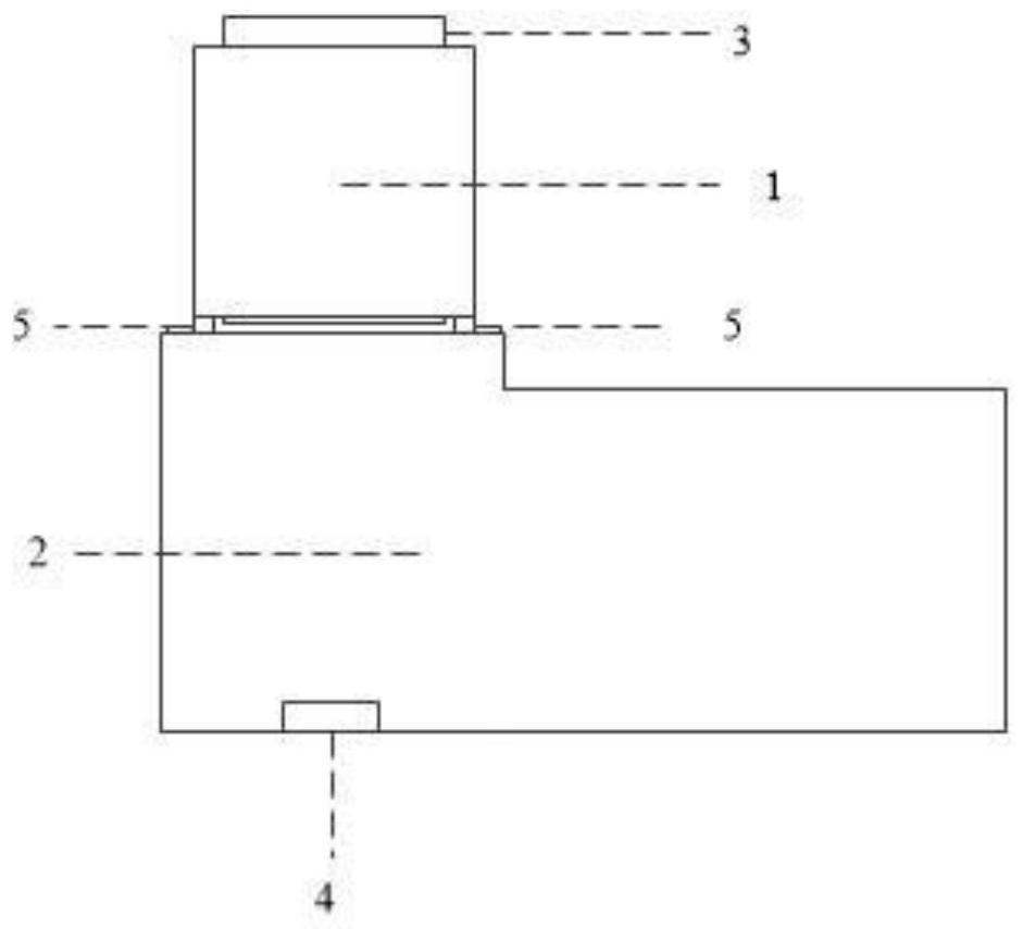
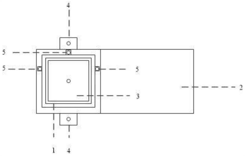
[0046] Such as Figure 2-Figure 5As shown, the radio frequency multi-frequency point test fixture includes a top cover shell 1, a base shell 2, a top cover inner core 3, a base inner core 6 and a base medium 7, the base shell 2 is fixed on the system base 10, and one side ...


PUM


Abstract

The invention discloses a multi-frequency-point radio frequency impedance and current testing system. The multi-frequency-point radio frequency impedance and current testing system comprises a radio frequency multi-frequency-point testing clamp and a radio frequency current probe, wherein a gap is formed between inner cores of a top cover shell, a pressure gauge is arranged on the inner core of atop cover, a base inner core is arranged in a base shell, a radio frequency signal injection end is arranged at the end of the base inner core, the radio frequency current probe and a device to be tested are placed at the boundary between the top cover shell and the base shell, and the device to be tested is located between the inner core of the top cover and the inner core of the base; a microstrip line is arranged on the top face of a T-shaped plate and connected with a vector network analyzer and the radio frequency current probe; and the T-shaped plate is provided with a coupling coil, andthe coupling coil is electrically connected with the microstrip line and the ground plane. The multi-frequency-point radio frequency impedance and current testing system overcomes the defect that thehigher harmonic signal testing capacity is insufficient in the actual testing process, the good transmission performance of the clamp to multiple frequency points is achieved, the electromagnetic compatibility problem is solved, radio frequency current information is obtained in the testing process, and the problem that devices such as foam cannot be accurately tested due to the irreversible characteristic of compression in the testing process is solved.

Description

technical field [0001] The invention relates to an impedance and current testing system of a test piece in the field of radio frequency test fixtures and radio frequency current probes, in particular to a multi-frequency point radio frequency impedance and current testing system. Background technique [0002] Gap shielding materials such as foam and conductive cloth are compressible and conductive, so they are widely used in gaps in mobile phones and various electronic and electrical equipment to provide conductive connection and electromagnetic shielding. [0003] This kind of electrical connection formed by foam and other materials has the nonlinearity of electrical connection contact, which will add the carrier signal and its nonlinear harmonic signal, resulting in passive intermodulation phenomenon, thus causing interference to the receiving passband and signal And influence, causing electromagnetic compatibility and electromagnetic interference problems, is a key proble...

Claims


Application Information

Patent Timeline
IPC IPC(8): G01R27/02G01R1/04G01R1/067G01R19/00
CPCG01R1/0408G01R1/06733G01R1/06755G01R19/0092G01R27/02
Inventor 李尔平王成铭陈泉坤封朝阳
Owner 海宁利伊电子科技有限公司
Why Eureka
Try Eureka