Process for coating fluorescent glue layer on surface of LED chip

A technology of LED chip and fluorescent adhesive layer, which is applied in the direction of surface coating liquid devices, coatings, semiconductor devices, etc., can solve the problems of high precision and consistency of the screw that is difficult to control, unstable air pressure, and uneven color of white light, etc., to achieve Reduce the generation of uneven light spots, improve the degree of standardization, and reduce the effect of chromaticity differences

Inactive Publication Date: 2021-01-01
GUANGZHOU JUHONG OPTOELECTRONICS
View PDF9 Cites 1 Cited by
  • Summary
  • Abstract
  • Description
  • Claims
  • Application Information

AI Technical Summary

Problems solved by technology

The disadvantage of this process is that in the actual production process, there will be factors such as unstable external air pressure and precipitation of phosphor powder, which will make the amount of glue coated on each LED chip inconsistent, which will eventually affect the color mixing of LED lamp beads. Consistency
The disadvantage of this process is that: LED chips are very small in size, so the amount of glue to be applied to each chip is also very small; the amount of glue delivered by the screw depends on the accuracy of the screw stroke. In the actual production process, it is difficult to The stroke of each movement of the control screw maintains high precision and consistency, so there is also the problem of uneven glue output
The defect of this process is similar to the screw drive, it is difficult to control the amount of glue extruded by each stroke of the probe is consistent
[0007] In addition, the above three processes are all completed with a single dispensing of glue. If the amount of glue in a single squeeze is too small, it will be difficult to completely cover the surface of the chip; if the amount of glue squeezed is too large, the fluorescent glue will stick to other parts of the LED lamp bead. It will affect the product yield and waste fluorescent glue
At the same time, a single dispensing will cause the fluorescent adhesive layer to be spherical, resulting in uneven thickness of the center and edge of the fluorescent adhesive layer, resulting in chromaticity differences between different lamp beads, resulting in uneven white light color, resulting in uneven light spots.

Method used


Image

  • Process for coating fluorescent glue layer on surface of LED chip
  • Process for coating fluorescent glue layer on surface of LED chip
  • Process for coating fluorescent glue layer on surface of LED chip

Examples


Embodiment Construction

[0034] Below, the present invention will be further described in conjunction with the accompanying drawings and specific implementation methods. It should be noted that, under the premise of not conflicting, the various embodiments described below or the technical features can be combined arbitrarily to form new embodiments. .

[0035] In describing the present invention, it should be understood that the terms "center", "length", "width", "thickness", "upper", "lower", "front", "rear", "left", " The orientation or positional relationship indicated by "right", "vertical", "horizontal", "top", "bottom", "inner", "outer", etc. is based on the orientation or positional relationship shown in the drawings, and is for convenience only The present invention is described and simplified descriptions do not indicate or imply that the device or element referred to must have a specific orientation, be constructed and operate in a specific orientation, and thus should not be construed as li...


PUM


Abstract

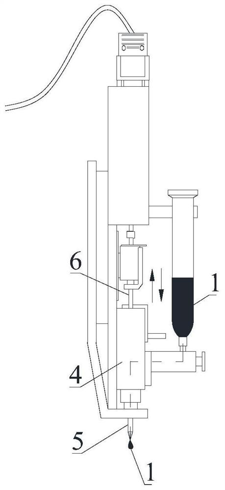
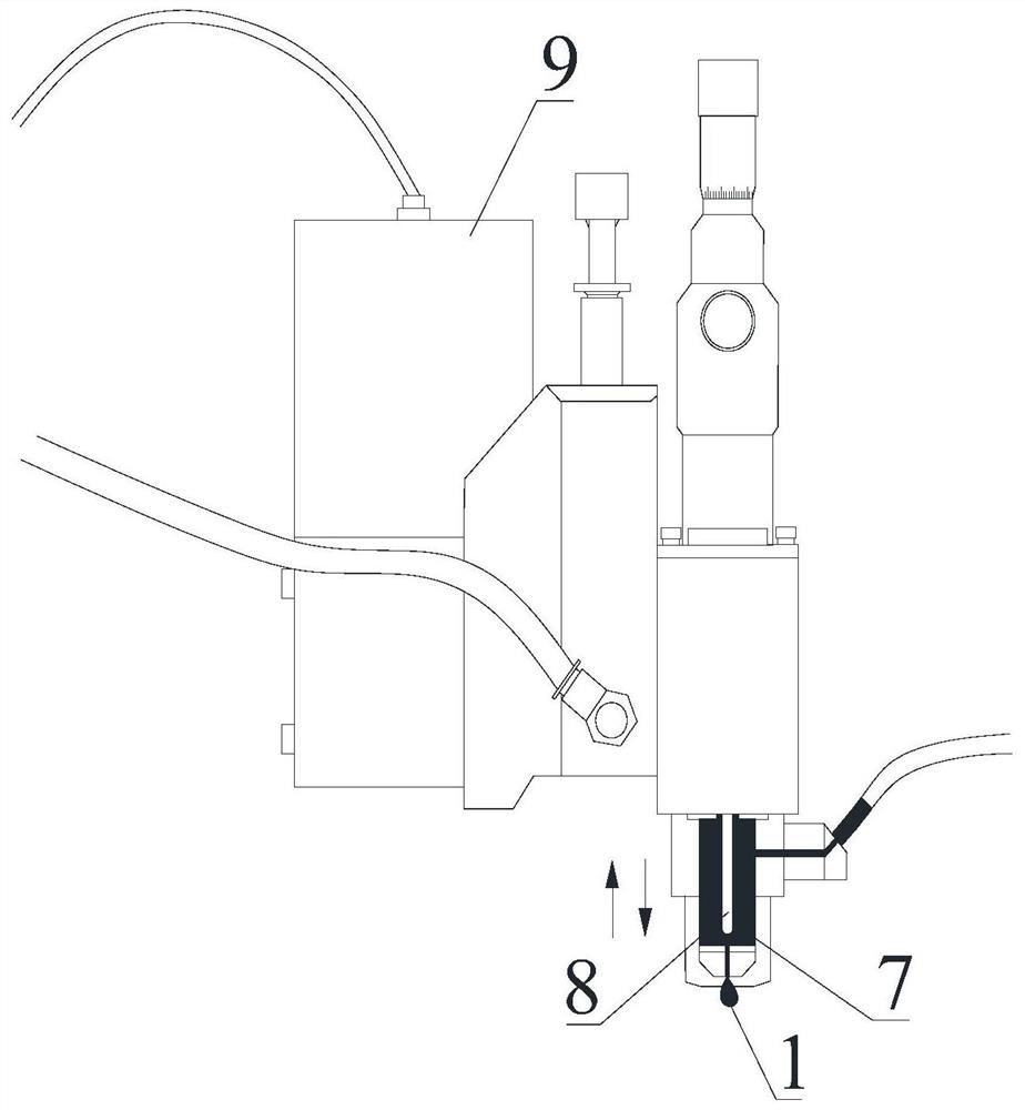
The invention discloses a process for coating a fluorescent glue layer on the surface of an LED chip. The process comprises a mounting step; a glue preparation step; a feeding step; a glue dipping step; a glue supplementing step; and a dispensing step. After the dispensing step is completed, the working cycle of the glue dipping step, the glue supplementing step and the dispensing step is repeatedfor multiple times until the surface of the LED chip is completely coated with the fluorescent glue layer. According to the process, coating is carried out in a multi-time dispensing manner, so thatthe coating amount of each chip can be accurately controlled, the situations of glue overflow and glue waste are avoided, and the cost is better saved; and by accurately controlling the amount of gluecoated on the LED chip, the consistency of the coating amounts of different LED lamp beads is ensured, so that the consistency of mixed color light of the LED lamp beads is ensured, and the standardization degree of large-batch products is improved.

Description

technical field [0001] The invention relates to the field of LED lamp beads, in particular to a process for coating a fluorescent adhesive layer on the surface of an LED chip. Background technique [0002] Light Emitting Diode (LED) is a solid-state semiconductor device. Because LED has the characteristics of mercury-free, small size, long life, fast response, environmental protection, energy saving, and high color saturation, its application is more and more It is becoming more and more widely, especially white LED, which is considered as the third-generation lighting source after incandescent lamps and fluorescent lamps, and is widely used in liquid crystal projection devices, mobile phone backlights, display screens, etc. Common white LEDs can be obtained by mixing phosphors excited by blue LED chips. The quality of phosphor coating technology directly affects the luminous performance of LEDs. The type and thickness of phosphors coated will affect the luminous efficiency,...

Claims


Application Information

Patent Timeline
Patent Type & Authority Applications(China)
IPC IPC(8): B05D1/28B05C1/02B05C11/10H01L21/67H01L33/50H01L33/52
CPCB05D1/28B05C1/02B05C11/1002H01L33/50H01L33/52H01L21/67253H01L2933/0041H01L2933/005
Inventor 谢锡龙谢锡强谢锡鸿赵京升
Owner GUANGZHOU JUHONG OPTOELECTRONICS
Why Eureka
Try Eureka