Fiber-optic gyroscope optical path assembly method based on tail fiber stress monitoring

A fiber optic gyroscope and stress monitoring technology, which is used in Sagnac effect gyroscopes, measuring devices, and force measurement by measuring the change of optical properties of materials when they are stressed. Pigtail stress and other problems, to achieve the effect of improving the assembly qualification rate, avoiding the instability of the gyro output signal or the short working cycle and simple operation

Pending Publication Date: 2021-01-01
HEBEI HANGUANG HEAVY IND
View PDF11 Cites 1 Cited by
  • Summary
  • Abstract
  • Description
  • Claims
  • Application Information

AI Technical Summary

Problems solved by technology

Due to the complexity of the fiber optic gyroscope assembly process, the existing fiber optic gyroscope optical path assembly method cannot effectively prevent the tail fiber stress, and the assembly pass rate is low

Method used


Image

  • Fiber-optic gyroscope optical path assembly method based on tail fiber stress monitoring
  • Fiber-optic gyroscope optical path assembly method based on tail fiber stress monitoring

Examples


Embodiment Construction

[0020] The present invention will be described in detail below with reference to the accompanying drawings and examples.

[0021] The invention is assembled based on the monitoring of the tail fiber stress during the optical path assembly of the optical fiber gyroscope. The design is reasonable and the operation is simple. It has been practically applied in the optical path assembly of a high-precision optical fiber gyroscope, which improves the qualified rate of one assembly and solves the mass production of optical fiber gyroscopes. key technologies in.

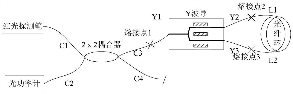
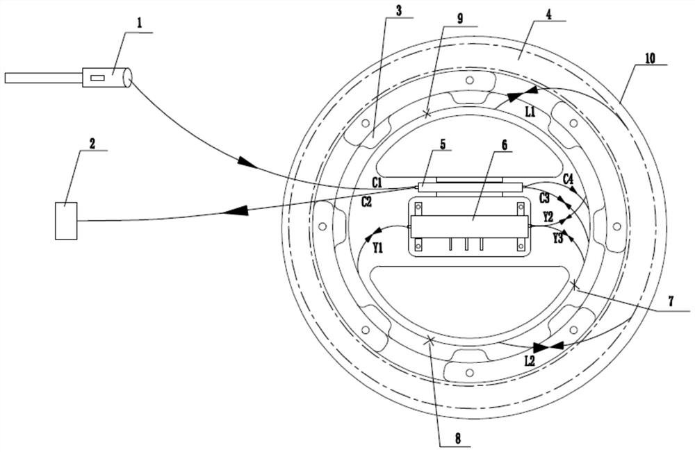
[0022] figure 1 For the test principle of the optical path pigtail stress of the present invention, the devices used for pigtail stress monitoring include a red light detection pen, a 2 × 2 fiber coupler, an optical fiber ring, a Y waveguide and an optical power meter, wherein the red light detection pen is used as the emission source of the optical path .

[0023] Described assembly method comprises the steps:

[0024] ...


PUM


Abstract

The invention provides a fiber-optic gyroscope optical path assembly method based on tail fiber stress monitoring, which can effectively monitor the existence of tail fiber stress and effectively prevent the tail fiber stress during assembly. According to the invention, the tail fiber stress is monitored during gyroscope assembly, the position of a device and the coiling direction of a tail fiberare convenient to adjust in time, the problem of unstable gyroscope output signals or short working period caused by the existence of optical fiber stress after gyroscope assembly is avoided, and theone-time assembly qualification rate is improved. The method is simple and effective to operate, is also suitable for other types of fiber-optic gyroscopes, especially for small or ultra-small fiber-optic gyroscopes with more complex assembly processes, and solves the key technology in batch production of fiber-optic gyroscopes.

Description

technical field [0001] The invention belongs to the technical field of fiber optic gyroscope optical path assembly, and in particular relates to an optical fiber gyroscope optical path assembly method based on tail fiber stress monitoring. Background technique [0002] With the continuous development of fiber optic technology, fiber optic gyroscopes have been widely used in military and civilian fields due to their large dynamic range, strong anti-interference ability, small size, light weight, simple structure, and low cost. Mass production has become the ultimate goal of manufacturers. When using various types of fiber optic gyroscope products, there are also some problems, such as unstable output signal or short service life of the gyroscope. The reasons are mainly concentrated in the matching of optical circuit devices and assembly process. The matching of the device can be solved by carrying out the matching test and test screening for the role of each device in the op...

Claims


Application Information

Patent Timeline
Patent Type & Authority Applications(China)
IPC IPC(8): G01C25/00G01C19/72G01L1/24
CPCG01C25/00G01C19/725G01L1/248
Inventor 胡文纲张红杰可伟
Owner HEBEI HANGUANG HEAVY IND
Why Eureka
Try Eureka