Auxiliary bathing equipment for patient with leg plaster
A plaster and leg technology, applied in the field of auxiliary bathing equipment for patients with plaster casts on the legs, can solve problems such as plaster wound infection, and achieve the effect of avoiding accidental falls
- Summary
- Abstract
- Description
- Claims
- Application Information
AI Technical Summary
Problems solved by technology
Method used
Image
Examples
Embodiment 1
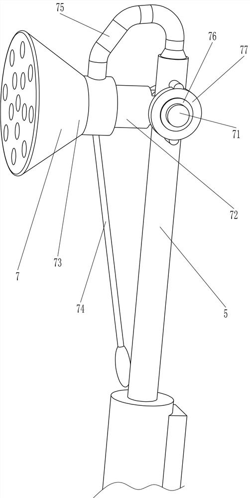
[0023] An auxiliary bathing device for a patient with plaster on the leg, such as Figure 1-Figure 3 As shown, it includes a bottom plate 1, a side plate 2, a fixed pipe 4, a water supply pipe 5, a fitting mechanism 6 and a water spray mechanism 7. The left and right sides and the rear side of the top of the bottom plate 1 are fixedly connected with the side plate 2, and the rear side plate 2. It is fixedly connected with the other two side plates 2. There is a drainage hole 3 on the right side of the rear of the bottom plate 1. The inner surface of the right side plate 2 is fixed with fixed pipes 4 symmetrically up and down. The fixed pipes 4 on the upper and lower sides are fixed with The water supply pipe 5 is fixedly connected with a bonding mechanism 6 on the left side of the top of the bottom plate 1 , and the upper part of the water supply pipe 5 is fixedly connected with a water spray mechanism 7 .
[0024] The bonding mechanism 6 includes a waterproof frame 61, a hing...
Embodiment 2
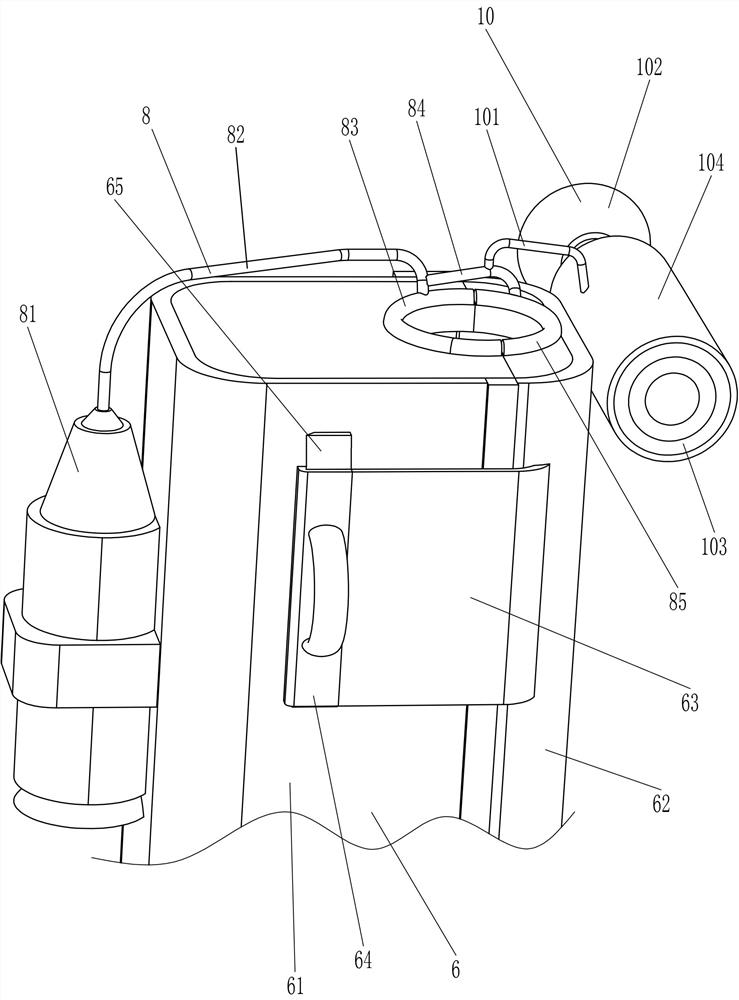
[0030] On the basis of Example 1, such as figure 2 As shown, a sealing mechanism 8 is also included. The sealing mechanism 8 includes an air pump 81, a first air pipe 82, a first sealing ring 83, a second air pipe 84 and a second sealing ring 85. There is an air pump 81, a first sealing ring 83 is fixedly connected to the right side of the outer top of the waterproof frame 61, a first air pipe 82 is fixedly connected to the top of the air pump 81, the tail end of the first air pipe 82 is fixedly connected to the first sealing ring 83, and the first air pipe 82 It communicates with the inside of the first sealing ring 83 , the outer top of the hinged cover 62 is fixedly connected with a second sealing ring 85 , and the rear side of the second sealing ring 85 is fixedly connected with a second air pipe 84 , and the second air pipe 84 communicates with the inside of the second sealing ring 85 , the tail end of the second trachea 84 is fixedly connected to the right side of the fir...
Embodiment 3
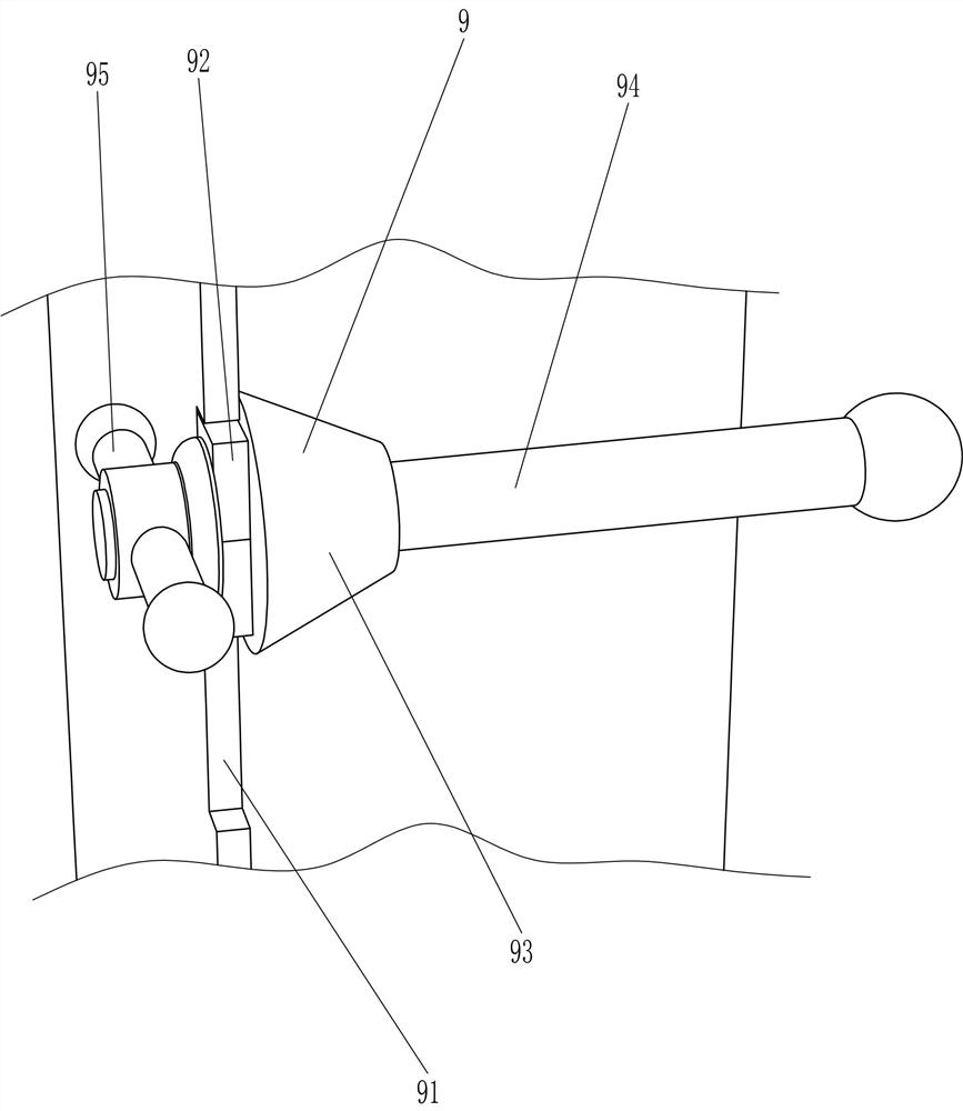
[0033] On the basis of embodiment 1 and embodiment 2, such as figure 2 with Figure 4 As shown, also include supporting mechanism 9, supporting mechanism 9 includes slide block 92, limit ring 93, screw rod 94 and handle 95, rear side plate 2 upper left side has chute 91, and the sliding type in chute 91 A slide block 92 is provided, the front side of the slide block 92 is fixedly connected with a limit ring 93, a screw rod 94 is fixedly connected between the middle part of the slide block 92 and the limit ring 93, and the rear part of the screw rod 94 is connected with a handle 95 by threaded rotation.
[0034] Also includes a force distribution mechanism 10, the force distribution mechanism 10 includes a shunt tube 101, a fixed seat 102, a tubular air bag 103 and a buffer pad 104, and the rear side plate 2 is fixedly connected with the fixed seat 102 in the middle of the lower side of the inner surface. The front portion of the seat 102 is covered with a tubular air bag 103...
PUM
 Abstract
Description
Claims
Application Information
 - R&D
- Intellectual Property
- Life Sciences
- Materials
- Tech Scout
- Unparalleled Data Quality
- Higher Quality Content
- 60% Fewer Hallucinations
Browse by: Latest US Patents, China's latest patents, Technical Efficacy Thesaurus, Application Domain, Technology Topic, Popular Technical Reports.
© 2025 PatSnap. All rights reserved.Legal|Privacy policy|Modern Slavery Act Transparency Statement|Sitemap|About US| Contact US: help@patsnap.com


