Glass cover plate flat plate cleaning equipment

A technology for cleaning equipment and glass cover plates, applied in lighting and heating equipment, removing smoke and dust, cleaning flexible objects, etc., can solve the problems of affecting the workshop environment, glass pollution, increasing the air knife, etc., to achieve high efficiency and avoid pollution effect

Inactive Publication Date: 2021-01-05
界首泰谷工业设计有限公司
View PDF1 Cites 9 Cited by
  • Summary
  • Abstract
  • Description
  • Claims
  • Application Information

AI Technical Summary

Problems solved by technology

For example the invention of patent No. CN102476924A just discloses a kind of flat glass washing machine, comprises upper cabinet, and its below is provided with elevator, and the bottom of elevator is provided with base, and upper cabinet includes a cleaning section and a drying section, above the drying section It is a centrifugal fan; the cleaning section includes a roller transmission mechanism, an upper brush, a lower brush, a nozzle and a water tank, and the top of the upper cabinet of the drying section, and the side adjacent to the cleaning section are sequentially provided with a wiper assembly, a straight air knife and Inclined air knife; the flat glass cleaning machine can scrape off most of the water droplets on the upper surface of the glass after cleaning through the wiper assembly, but it is impossible to clean the glass 100% during the front cleaning process, especially for There will still be residual impurities on the surface of the chemically tempered glass. When the wiper scrapes off the cleaning fluid on the upper surface of the glass, it will scrape up a small amount of impurities remaining on the glass surface and attach them to the lower end of the wiper. The impurities on the wiper board will gradually accumulate when the whole flat panel washing machine runs for a long time. When the impurities on the wiper board accumulate to a certain amount, it will pollute the glass after subsequent washing. Therefore, it is necessary to stop frequently to clean the wiper board. to clean
In addition, the wiper has a limited effect on removing residual water on the glass surface. To improve the efficiency of the entire cleaning equipment, it is still necessary to increase the wind force sent into the air knife, and to increase the wind force in the air knife requires a higher power fan, and Excessive wind force will cause excessive noise in the air knife, affecting the entire workshop environment

Method used


Image

  • Glass cover plate flat plate cleaning equipment
  • Glass cover plate flat plate cleaning equipment
  • Glass cover plate flat plate cleaning equipment

Examples


Embodiment 1

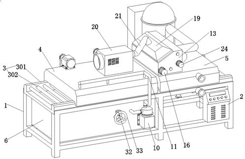
[0034] This embodiment 1 has introduced a kind of flat plate cleaning equipment for glass cover, refer to the attached figure 1 And attached figure 2 , which includes a frame 1 and a control cabinet 2, and the control cabinet 2 is arranged at the right end of the frame 1. The upper end of frame 1 is provided with roller table conveying mechanism 3, and its roller table conveying mechanism 3 is prior art, and specifically it comprises two crate boxes 301 before and after, and equidistant rotation is provided with between two crate boxes 301 There are a plurality of drive rollers 302, and the outer surface of the drive rollers 302 is covered with a rubber skin layer, and the crate 301 is provided with a power device (not shown) that drives each drive roller 302 to rotate.

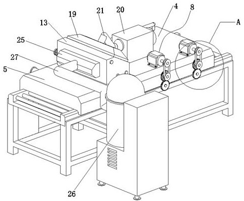
[0035] Reference attached figure 1 And attached image 3 , a cleaning box 4 is arranged on the left end of the roller conveyor mechanism 3, an air-drying box 5 is arranged on the roller conveyor mechanism...

Embodiment 2

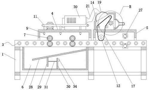
[0040] Embodiment 2 is an improvement made to the interior of the water tank on the basis of Embodiment 1. The same parts of Embodiment 2 and Embodiment 1 will not be described again. The difference is that, refer to the attached image 3 , the upper end opening of the water tank 6 is arranged, and the upper end opening of the water tank 6 is arranged directly below the cleaning tank 4 . In this embodiment, the right side wall of the water tank 6 is provided with a water deflector 28 which is set low on the left and high on the right. Riser 29 is arranged, and a gap is also left between the riser 29 and the bottom wall of the water tank 6, and then a dividing plate 30 is connected on the water tank 6 bottom wall positioned at the right side of the rising plate 29, and the gap between the rising plate 29 and the dividing plate 30 The setting can achieve the effect similar to that of a U-shaped liquid level gauge, and then a filter cloth 31 is arranged between the vertical plate...


PUM


Abstract

The invention relates to the technical field of glass cleaning equipment, and particularly discloses glass cover plate flat plate cleaning equipment. The glass cover plate flat plate cleaning equipment comprises a rack and a control cabinet, a roller way conveying mechanism is arranged at the upper end of the rack, a cleaning box is arranged at the left end of the roller way conveying mechanism, an air drying box is arranged on the roller way conveying mechanism located on the right side of the cleaning box, a wiping roller is rotationally arranged at the left end of an inner cavity of the airdrying box, a drying box is arranged on the upper surface of the air drying box, a driving roller and a driven roller are arranged in the interior of the the drying box, a conveying cloth belt is arranged among the wiping roller, the driving roller and the driven roller, and a water absorbing layer is arranged on the outer surface of the conveying cloth belt in a compounded mode. According to theglass cover plate flat plate cleaning equipment, a scraper assembly in a traditional flat plate cleaning machine is replaced with the conveying cloth belt provided with the water absorbing layer in acompounding mode, 95% of cleaning liquid on a glass cover plate can be absorbed away by the water absorbing layer in the wiping process, the effect of removing the cleaning liquid on the upper surface of the glass cover plate is better, and therefore under the condition that the wind power fed into an air knife is the same, the efficiency of glass cover plate cleaning is higher, and the efficiency of the drying box is higher.

Description

technical field [0001] The invention relates to the technical field of glass cleaning equipment, and specifically discloses a glass cover plate cleaning equipment. Background technique [0002] As the name suggests, the glass cover is a cover made of glass, which is mainly used as a glass component on electronic equipment such as the outer screen of the notebook computer, the outer screen of the tablet computer, and the upper surface of the electronic weight scale. The glass cover plate has been cut, polished and other processes in the process of processing, and then it is sent to a flat-panel cleaning machine to clean up impurities on its surface. [0003] At present, the common flat-panel cleaning machines on the market send the glass cover plate into the cleaning chamber by a group of horizontal conveying rollers. The cleaning chamber is equipped with a washing nozzle, several groups of cleaning brush rollers and scrapers symmetrical up and down. The upper and lower surf...

Claims


Application Information

Patent Timeline
Patent Type & Authority Applications(China)
IPC IPC(8): B08B11/04B08B1/00B08B1/02B08B3/02B08B3/08B08B13/00B08B15/04F26B5/16F26B15/12F26B21/00
CPCB08B1/002B08B1/02B08B3/022B08B3/08B08B11/04B08B13/00B08B15/04F26B5/16F26B15/122F26B21/004
Inventor 余秀芳
Owner 界首泰谷工业设计有限公司
Why Eureka
Try Eureka