Rapid in-mold simulation surface decoration process

A thermal process and molding process technology, applied in the field of rapid in-mold simulation surface decoration process, can solve the problems of environmental pollution, labor input, high cost of material resources, cumbersome processes, etc. in the spraying process, so as to improve the aesthetic texture and fashionability, and improve the process process. The effect of low energy consumption and environmental protection in the process

Pending Publication Date: 2021-01-05
长春恒兴集团有限公司
View PDF0 Cites 0 Cited by
  • Summary
  • Abstract
  • Description
  • Claims
  • Application Information

AI Technical Summary

Problems solved by technology

It can be seen that the traditional injection molding spraying process has cumbersome steps and the whole process is relatively complicated, which results in high energy consumption, high manpower and material costs in the process, and the spraying process pollutes the environment and is not environmentally friendly.
On the other hand,

Method used


Image

  • Rapid in-mold simulation surface decoration process
  • Rapid in-mold simulation surface decoration process
  • Rapid in-mold simulation surface decoration process

Examples


Embodiment Construction

[0031] In order to make the purpose, technical solutions and advantages of the embodiments of the present invention clearer, the technical solutions of the embodiments of the present invention will be clearly and completely described below. Apparently, the described embodiments are some, not all, embodiments of the present invention. Based on the described embodiments of the present invention, all other embodiments obtained by persons of ordinary skill in the art without creative efforts shall fall within the protection scope of the present invention.

[0032] Unless otherwise defined, the technical terms or scientific terms used in the present invention shall have the common meanings understood by those skilled in the art to which the present invention belongs.

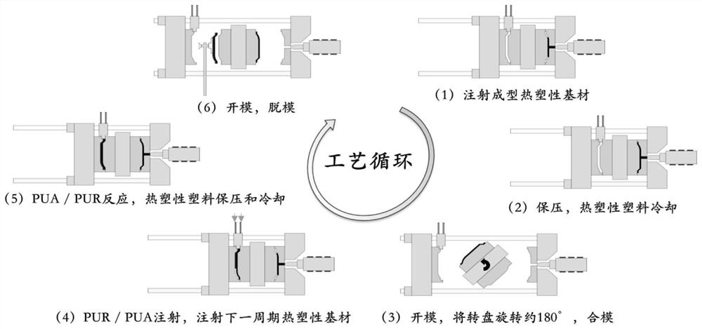
[0033] Reaction Injection Molding Process

[0034] figure 1 A schematic diagram of the steps in the reaction injection molding process according to the present invention is shown. In the reaction injection mold...


PUM


Abstract

The invention belongs to the field of automobile part manufacturing processes, and particularly relates to a rapid in-mold simulation surface decoration process. The forming process of an injection molding part comprises the following steps that a thermoplastic base material is subjected to injection molding in a first mold cavity through a rapid cooling and rapid heating process to form the highlight injection molding part, wherein nanometer or femtosecond laser textures are pre-machined on the inner surface of the first mold cavity so that the highlight injection molding part can have a nanometer or femtosecond laser texture structure; the first mold cavity is quenched and opened, a rotary table is approximately rotated by 180 degrees, and a second mold cavity is closed; the highlight injection molding part is directly cast and coated with a two-component coating in the second mold cavity, and the two-component coating reacts and is cured in the second mold cavity, so that a transparent coating is formed on the surface of the highlight injection molding part; and the second mold cavity is cooled and opened, and the highlight injection molding part with the nanometer or femtosecond laser texture structure and the scratch-resistant surface is formed. The rapid in-mold simulation surface decoration process has the obvious cost advantage, and the surface coating of the formed highlight injection molding part is attractive, ideal in hardness and good in scratch resistance; and in addition, due to the combination of the nanometer or femtosecond laser texture structure and the external transparent coating, the highlight injection molding part has a three-dimensional decorative effect on the whole, and the product has more advantages and competitiveness.

Description

technical field [0001] The invention belongs to the field of manufacturing technology of auto parts, and in particular relates to a fast in-mold simulation surface decoration technology. Background technique [0002] In recent years, the automobile industry has developed rapidly, especially the output and social ownership of cars have maintained a relatively high growth rate. Plastics for automobiles play an irreplaceable role in satisfying aesthetics, safety, and lightweight. At the same time, new technologies for automobiles are also It is developing towards a more environmentally friendly, safer, more comfortable and personalized direction. [0003] At present, the injection molding and spraying process is mostly used for automotive decorative parts. The whole process includes at least injection molding, spraying, and final assembly, and each individual link includes several specific small links. It can be seen that the traditional injection molding spraying process has ...

Claims


Application Information

Patent Timeline
IPC IPC(8): B29C45/16B29C45/26B29C45/78B29C33/42B29C45/73
CPCB29C33/42B29C45/1628B29C45/26B29C45/73B29C45/78
Inventor 范世永徐刚
Owner 长春恒兴集团有限公司
Why Eureka
Try Eureka