Continuous vacuum sintering furnace

A vacuum sintering furnace and vacuum technology, applied in the field of sintering furnace, can solve the problems of low reliability, high maintenance cost, complicated operation, etc., and achieve the effects of eliminating waveform distortion, shortening sintering time, and uniform temperature

Inactive Publication Date: 2021-01-05
JIANGXI KAIYUAN AUTOMATIC EQUIP CO LTD
View PDF13 Cites 2 Cited by
  • Summary
  • Abstract
  • Description
  • Claims
  • Application Information

AI Technical Summary

Problems solved by technology

The advantage of the single-chamber vacuum sintering furnace is that the price is moderate, and the disadvantages are: high energy consumption, complicated operation, and more labor
The multi-chamber continuous sintering furnace is expensive, because each chamber needs a transmission mechanism and a gate valve partition, which makes the overall structure complex, resulting in low reliability and high maintenance costs
[0004] Patent CN20181141365.7 discloses an externally heated continuous sintering furnace. Although the above-mentioned problems are solved, the following problems arise at the same time: 1. Only products below 1050 degrees can be sintered. The heat-resistant steel currently on the market can only be reliably work at this temperature
2. The diameter of the furnace is difficult to exceed 500mm

Method used


Image

  • Continuous vacuum sintering furnace
  • Continuous vacuum sintering furnace
  • Continuous vacuum sintering furnace

Examples


Embodiment

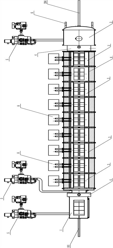
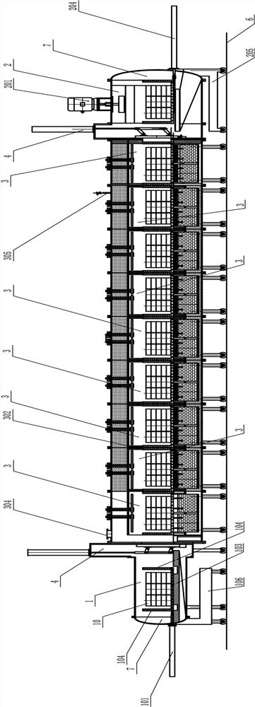
[0046] Such as Figure 1 to Figure 10As shown, a continuous vacuum sintering furnace includes a vacuum furnace-in preparation chamber 1, a sintering chamber 3 with multiple temperature zones, and an air-cooling chamber 2 connected in sequence, and the vacuum-in furnace preparation chamber 1 and air-cooling chamber 2 One end is provided with a gate valve 4; through the gate valve 4, the vacuum enters the furnace preparation chamber 1, the sintering chamber 3 with multiple temperature zones and the air cooling chamber 2 to form three independent spaces respectively;

[0047] The vacuum furnace preparation chamber 1, the sintering chamber 3 and the air cooling chamber 2 are all connected with a vacuum unit 5;

[0048] The vacuum furnace preparation chamber 1, the sintering chamber 3 and the air cooling chamber 2 are all provided with guide rails 6;

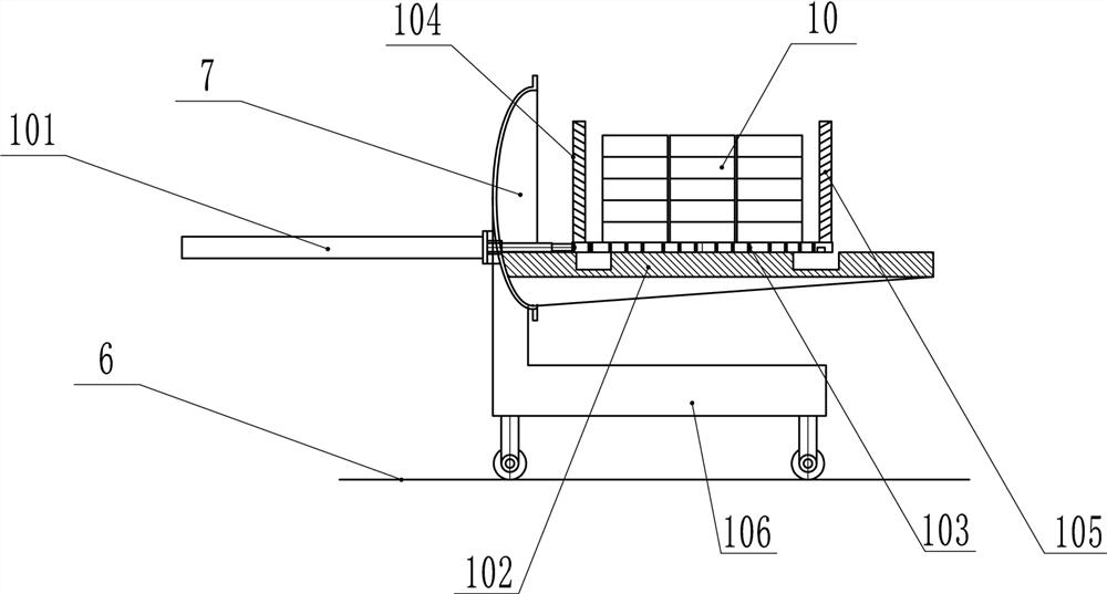
[0049] Such as image 3 As shown, the vacuum furnace preparation chamber 1 is provided with a pusher cylinder 101, a preparation ...


PUM


Abstract

The invention belongs to the technical field of sintering furnaces, and particularly relates to a continuous vacuum sintering furnace. The continuous vacuum sintering furnace comprises a vacuum furnace-entering preparation chamber, a sintering chamber with a plurality of temperature zones and an air cooling chamber which are sequentially communicated, wherein a gate valve is arranged at one end ofthe vacuum furnace-entering preparation chamber and one end of the air cooling chamber; the vacuum furnace-entering preparation chamber, the sintering chamber with the plurality of temperature zonesand the air cooling chamber respectively form three independent spaces through the gate valves; the vacuum furnace-entering preparation chamber, the sintering chamber and the air cooling chamber are respectively communicated with a vacuum unit and are respectively provided with a guide rail; a material pushing oil cylinder, a preparation chamber bracket and a sintering material frame are arrangedin the vacuum furnace-entering preparation chamber; and tray heat insulation plugs are arranged on two end sides of the sintering material frame. Since there is no partition in the sintering chamber,a vacuum unit is used in common, and there is no conveying mechanism in the sintering chamber, so that the overall complexity is greatly reduced, and the cost is reduced. Heating bodies are arranged at the periphery and the center of the interior of the sintering chamber, so that the heat transfer distance is shortened by one time, the temperature uniformity speed is increased, and the sintering time is shortened.

Description

technical field [0001] The invention belongs to the technical field of sintering furnaces, and in particular relates to a continuous vacuum sintering furnace. Background technique [0002] The continuous sintering furnaces of the current technology are all multi-chamber thermal type, and some even have more than ten chambers. Its advantages are: energy saving, high efficiency, and stable products; but because of its complex structure, high failure rate, and high cost, these limit the use of continuous furnaces. In fact, more than 85% of the current market is still using a single-chamber vacuum sintering furnace. The advantage of the single-chamber vacuum sintering furnace is that the price is moderate, and the disadvantages are: high energy consumption, complicated operation, and more labor. Because of the internal heating type, the insulation material will absorb the moisture in the air when the furnace door is opened, resulting in pollution of the furnace body. [0003]...

Claims


Application Information

Patent Timeline
Patent Type & Authority Applications(China)
IPC IPC(8): F27B9/04F27B9/26F27B9/12F27B9/30F27B9/36F27B9/40
CPCF27B9/042F27B9/26F27B9/12F27B9/30F27B9/36F27B9/40F27B2009/126F27B2009/305F27M2003/04
Inventor 袁志龙李平澜董永安郑方
Owner JIANGXI KAIYUAN AUTOMATIC EQUIP CO LTD
Why Eureka
Try Eureka