Reconfigurable optical filter based on micro-ring array

A technology of optical filter and microring waveguide, which is applied in the field of optical fiber communication and integrated photonics, can solve the problem of single filtering function of the filter, achieve the effect of realizing diversity and improving dynamic flexibility

Active Publication Date: 2021-01-05
HUAZHONG UNIV OF SCI & TECH
View PDF6 Cites 8 Cited by
  • Summary
  • Abstract
  • Description
  • Claims
  • Application Information

AI Technical Summary

Problems solved by technology

[0004] In view of the above defects or improvement needs of the prior art, the present invention provides a reconfigurable filter based on a microring array, the purpose of which is to introduce an optical coupler structure with reconfigurable switching states in the coupling region of the microring array , can independently control whether the coupling effect occurs in each coupling area, and then design and combine the switching states of each coupling area, thereby solving the technical problem of single filtering function of the filter based on the micro-ring structure

Method used


Image

  • Reconfigurable optical filter based on micro-ring array
  • Reconfigurable optical filter based on micro-ring array
  • Reconfigurable optical filter based on micro-ring array

Examples


Embodiment 1

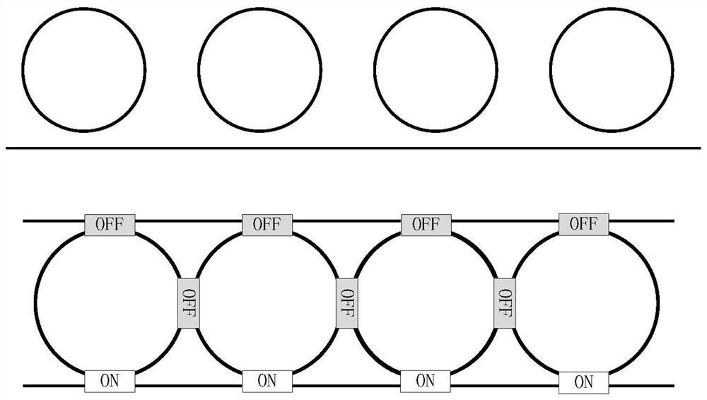
[0046] image 3 It is the equivalent structure diagram of the straight-through multi-ring cascading topology proposed by the present invention and the switch state diagram of each coupling area. Such as image 3 As shown, the feature of the straight-through multi-ring cascaded topology is that all micro-rings are only coupled to the same bus waveguide, and there is no coupling between micro-rings. Its basic structure is as follows image 3 shown in the figure above. The switching state of each coupling region in the corresponding four-ring reconfigurable optical filter is as follows image 3 as shown in the figure below. It can be seen that when the working state of the coupling regions between the four microrings and the first bus waveguide and the coupling region between the microrings is set to off, it can correspond to the straight-through multi-ring cascade topology, and obtain at the output Corresponding notch filter characteristics.

Embodiment 2

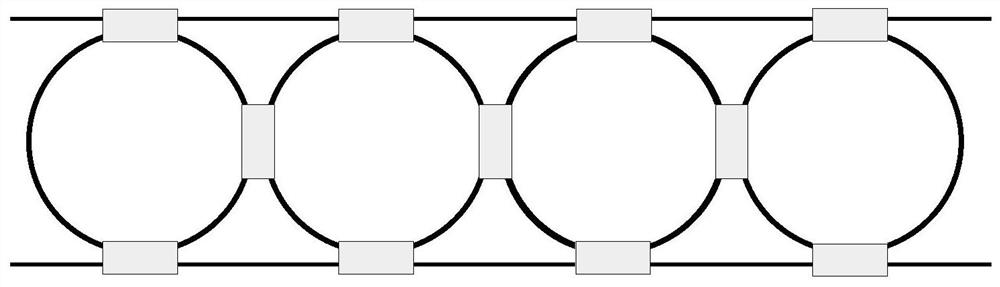
[0048] Figure 4 It is an equivalent structural diagram of uploading and downloading multi-ring cascading in topology proposed by the present invention and a schematic diagram of switch states of each coupling area. Such as Figure 4 As shown, the upload and download type multi-ring cascade topology is characterized in that all microrings are coupled with the first bus waveguide and the second bus waveguide, but there is no coupling between the microrings, and its basic structure is as follows Figure 4 shown in the figure above. The switching state of each coupling region in the corresponding four-ring reconfigurable optical filter is as follows Figure 4 As shown in the figure below, it can be seen that when only the working state of the coupling area between the four microrings is set to off, the corresponding upload and download multi-ring cascade topology can be obtained, and the corresponding notch can be obtained at the through end Filtering characteristics, the corr...

Embodiment 3

[0050] Figure 5 It is the equivalent structure diagram of the multi-ring series topology proposed by the present invention and the schematic diagram of the switching state of each coupling area. Such as Figure 5 As shown, the multi-ring series topology is characterized by coupling between adjacent microrings, and only the first microring and the last microring are coupled with the first bus waveguide and the second bus waveguide respectively, and the rest of the microrings are not coupled with the Bus waveguide coupling. Its basic structure is as Figure 5 As shown in the figure above, the switch state of each coupling region in the corresponding four-ring reconfigurable optical filter is as follows Figure 5 As shown in the figure below, it can be seen that when the working status of the coupling area between the first three microrings and the first bus waveguide and between the last three microrings and the second bus waveguide is set to off, the remaining When the cou...


PUM


Abstract

The invention discloses a reconfigurable optical filter based on a micro-ring array, and belongs to the technical field of optical fiber communication and integrated photonics. The filter comprises afirst bus waveguide, a second bus waveguide and a plurality of micro-rings; the plurality of micro-rings are connected in parallel by the first bus waveguide and the second bus waveguide; the plurality of micro-rings are arranged between the first bus waveguide and the second bus waveguide at equal intervals; coupling regions are arranged between the micro-rings and the first bus waveguide; coupling regions are arranged between the micro-rings and the second bus waveguide; coupling regions are arranged between adjacent micro-rings; each coupling region is provided with a reconfigurable opticalcoupler, and the on-off state of the reconfigurable optical coupler can be independently regulated and controlled. The optical coupler structure with the reconfigurable on-off state is introduced into the coupling regions of the micro-ring array, whether the coupling action occurs in each coupling region or not can be independently controlled, various topological structures can be realized in theone-dimensional micro-ring array by designing and combining the on-off states of all coupling regions, and the diversity of a filtering function is realized.

Description

technical field [0001] The invention belongs to the technical field of optical fiber communication and integrated photonics, and more specifically relates to a reconfigurable optical filter based on a microring array. Background technique [0002] Optical communication is one of the most important ways of modern information and transmission, and it is moving towards the direction of ultra-high speed, large capacity, large broadband, long distance, and low cost. Optical filters play an important role in making full use of the wavelength resources of optical networks and protecting the maximum unimpeded channels in the network system. They are important devices in all-optical signal processing and wavelength division multiplexing systems. Microring filter is a kind of optical filter. Filters based on passive microrings, such as silicon and silicon nitride microrings, use the amplitude response and phase response characteristics of the microrings to process optical signals to ...

Claims


Application Information

Patent Timeline
Patent Type & Authority Applications(China)
IPC IPC(8): G02B6/293
CPCG02B6/29343
Inventor 张敏明姚欣怡刘德明
Owner HUAZHONG UNIV OF SCI & TECH
Why Eureka
Try Eureka