Gear forming device

A technology of forming device and gear, applied in the direction of gear tooth manufacturing device, belt/chain/gear, gear tooth, etc., can solve the problem of inability to stably cool the hob, and achieve the effect of good cooling effect, quality improvement, and quality assurance

Pending Publication Date: 2021-01-08
CHONGQING RUNYUE MACHINERY CO LTD
View PDF6 Cites 0 Cited by
  • Summary
  • Abstract
  • Description
  • Claims
  • Application Information

AI Technical Summary

Problems solved by technology

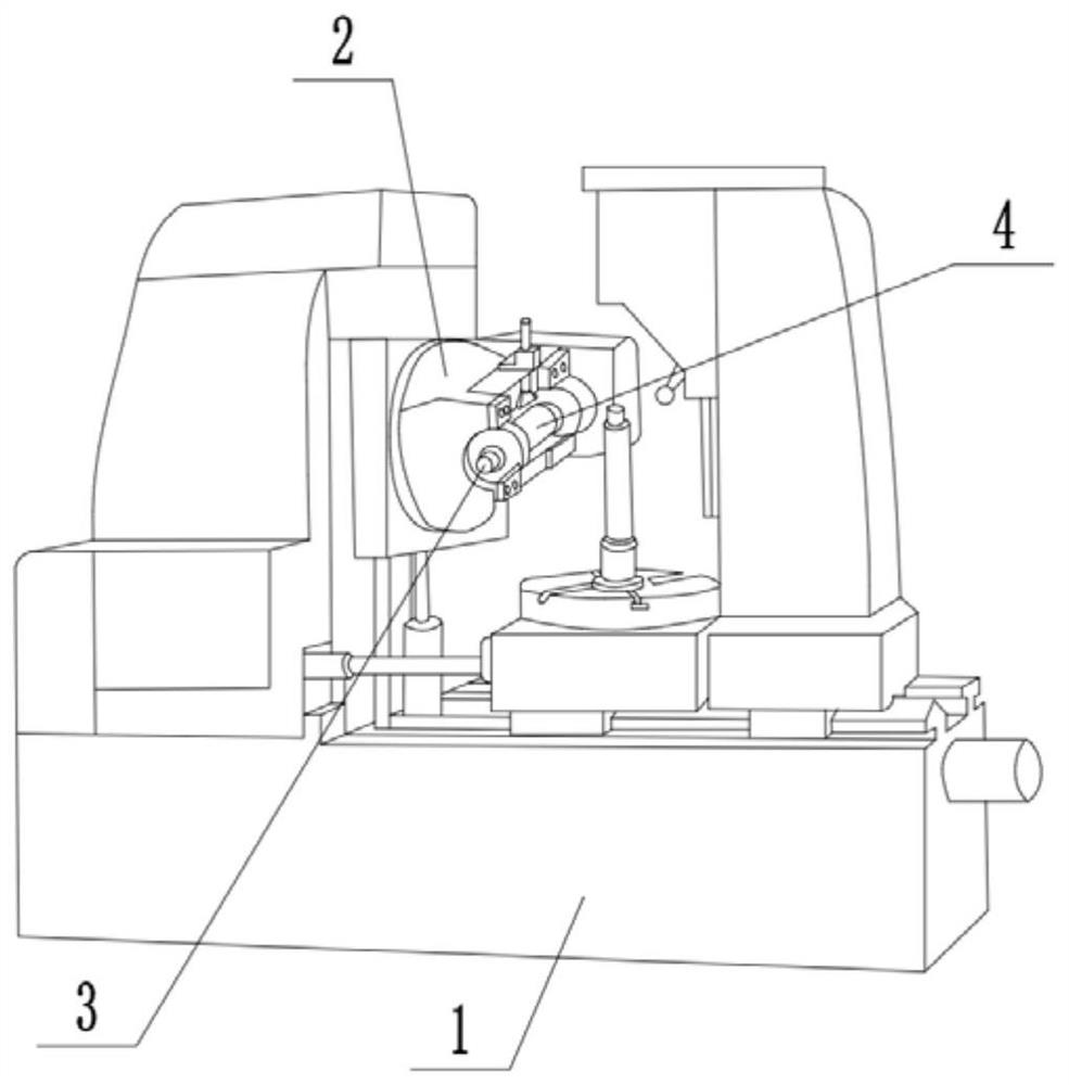
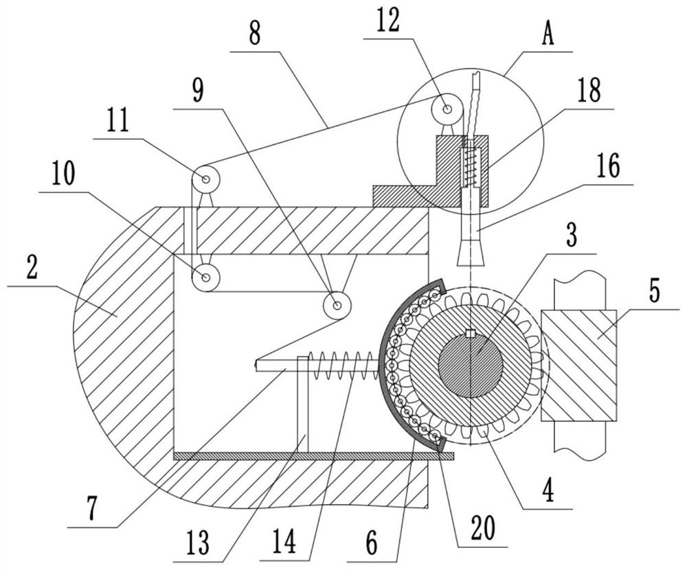
[0005] The present invention intends to provide a gear forming device to solve the problem in the prior art that the cooling pipe on the gear hobbing machine cannot provide stable cooling for hobs of different sizes after the hob is replaced

Method used


Image

  • Gear forming device
  • Gear forming device
  • Gear forming device

Examples


Embodiment 2

[0047] The difference between embodiment two and embodiment one is: as Figure 4 As shown, a second nozzle 21 is integrally formed near the bottom end of the first nozzle 16, and the second nozzle 21 faces the blank 5. When the cooling pipe 15 supplies cooling oil to the first nozzle 16, part of the cooling oil will flow from the second The nozzle 21 sprays towards the blank 5, so that the blank 5 is cooled and lubricated during processing, and at the same time, the cooling oil sprayed from the second nozzle 21 is used to clean the blank 5, so as to avoid the debris generated by cutting from adhering to the blank 5 outer wall and cause interference to hob 4 cutting blank 5.

[0048] Such as Figure 5 As shown, the first nozzle 16 and the second nozzle 21 are uniformly formed with a plurality of splitters 22, and the adjacent splitters 22 are fixedly connected with the flow guides 23 perpendicular to the flow splitters 22, and the adjacent flow guides 23 There is an included ...


PUM


Abstract

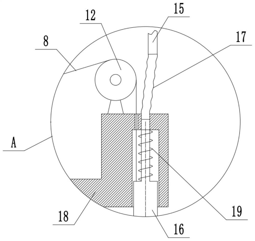
The invention relates to the technical field of gear machining equipment, and discloses a gear forming device. The gear forming device comprises a cutter fixing seat and a hob shaft rotationally connected to the cutter fixing seat, wherein a hob is detachably connected to the hob shaft, an arc-shaped plate is slidably connected to the cutter fixing seat in the radial direction of the hob shaft, the arc-shaped plate and the hob shaft are coaxially arranged, and a first elastic piece is arranged between the arc-shaped plate and the cutter fixing seat; and a cooling assembly facing the hob shaftis slidably connected to the cutter fixing seat, a connecting mechanism used for driving the cooling assembly to move along with the arc-shaped plate is connected between the cooling assembly and thearc-shaped plate, and under the transmission action of the connecting mechanism, the cooling assembly and the arc-shaped plate are the same in the radial movement trend relative to the hob shaft. According to the gear forming device, the connecting mechanism is arranged so that the distance between the cooling assembly and the hob shaft can be changed along with the change of the size of the replaced hob, and the problem that in the prior art, a cooling pipe cannot provide stable cooling for hobs with different sizes after the hob is replaced is solved.

Description

technical field [0001] The invention relates to the technical field of gear processing equipment, in particular to a gear forming device. Background technique [0002] As a mechanical element that transmits motion and power through continuous meshing of gear teeth, gears are widely used in automobiles, ships, machine tools and other fields. In the prior art, the processing of gears is generally completed by hobbing machines. Before processing, steel bars are cut into billets of appropriate length, and then the billets are fixed on the hobbing machine, and the hobbing machine is used to gradually complete the process. The processing of the blank finally makes the blank form a gear, and then the finished gear is obtained through grinding and heat treatment. [0003] In the process of processing gears with gear hobbing machines, since a large amount of heat will be generated during the processing, it is necessary to use cooling pipes to continuously spray cooling oil on the ho...

Claims


Application Information

Patent Timeline
IPC IPC(8): B23F23/00B23Q11/10B23F5/20
CPCB23F23/00B23Q11/10B23F5/20
Inventor 曾义杰
Owner CHONGQING RUNYUE MACHINERY CO LTD
Why Eureka
Try Eureka