Household garbage collecting and treating equipment

A technology for processing equipment and domestic waste, applied in the direction of garbage collection, trash cans, household appliances, etc., can solve the problems of large living garbage gap, domestic garbage dumping, environmental pollution, etc., and achieve the effect of reducing space, stable storage and transportation

Inactive Publication Date: 2021-01-08
张静
View PDF0 Cites 2 Cited by
  • Summary
  • Abstract
  • Description
  • Claims
  • Application Information

AI Technical Summary

Problems solved by technology

[0003] Domestic garbage contains a lot of water, which will breed a large number of bacteria, affect people's health, and easily produce stench, leading to environmental pollution, and the gap between living garbage is large, generally for the convenience of transportation, compression equipment is often used for compression. However, compressed household garbage is prone to dumping when temporarily stacked; for this reason, the present invention proposes a household garbage collection and treatment device that can solve the above problems

Method used


Image

  • Household garbage collecting and treating equipment
  • Household garbage collecting and treating equipment
  • Household garbage collecting and treating equipment

Examples


Embodiment 1

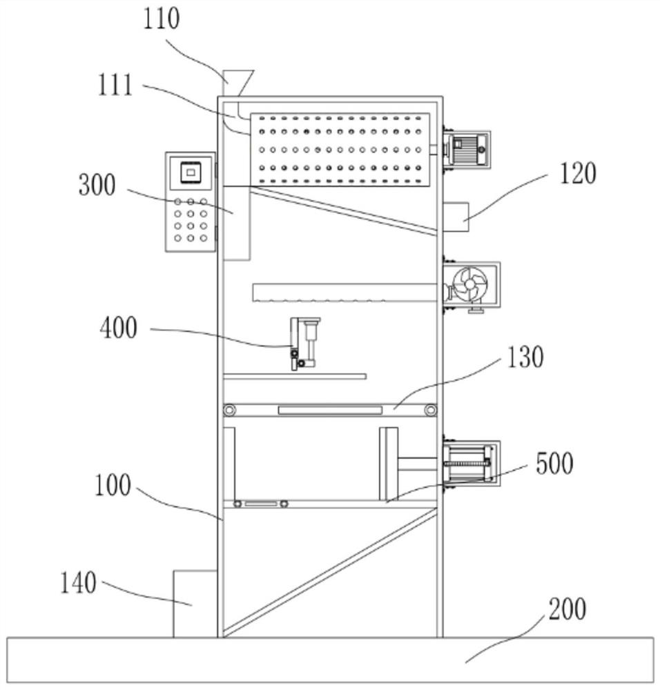
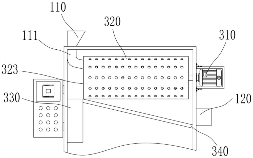
[0038] see Figure 1-14 , the present invention provides a technical solution: a domestic garbage collection and treatment equipment, including a fixed seat 200, the upper end of the fixed seat 200 is provided with a treatment box 100, the upper end of the treatment box 100 is provided with a feed port 110, and the right side of the treatment box 100 is provided with a The water outlet 120, the bottom left side of the treatment box 100 is provided with a discharge port 140; the feed inlet 110 is connected with a feed pipe 111 in the treatment box 100, and the feed pipe 111 is arranged obliquely, and the feed pipe 111 is connected from the first-level discharge port 323 extends to the right side of the drum 320;

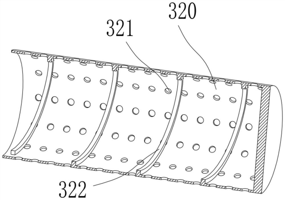
[0039] The water removal mechanism 300, the water removal mechanism 300 comprises the first motor 310 arranged on the outer wall of the right side of the processing box 100 and the cylinder 320 arranged in the treatment box 100, the first motor 310 is driven and conne...

Embodiment 2

[0042] drying mechanism 400, see Figure 1-3 , the drying mechanism 400 includes a drying plate 410 arranged on the bottom of the water removal mechanism 300, a hot air blower 420 arranged on the right side wall of the processing box 100, and a second motor 460 arranged on the outer wall of the front side of the processing box 100, and the drying plate 410 Horizontally installed, the right side of the drying plate 410 is provided with a secondary discharge port 411, and a hot air pipe 430 is provided above the drying plate 410. The hot air pipe 430 is connected to the hot air blower 420, and there are several air outlets on the lower side of the hot air pipe 430. 431, a moving plate 440 is arranged above the drying plate 410, the lower end of the moving plate 440 is hinged with a scraper 450 through the movable assembly 443, the upper end of the moving plate 440 is provided with a mounting plate 441, and the lifting hydraulic cylinder 442 is arranged on the mounting plate 441, ...

Embodiment 3

[0045] Compression mechanism 500, compression mechanism 500 comprises the collecting plate 510 that is arranged on drying mechanism 400 below and the extruding hydraulic cylinder 520 that is arranged on the outer wall on the right side of treatment box 100, and collecting plate 510 is horizontally arranged, and the left side of upper end of collecting plate 510 A baffle plate 530 is provided, and several groove bodies 531 are arranged at intervals on the right side wall of the baffle plate 530, and an extruding plate 540 is arranged on the right side of the upper end of the collecting plate 510, and several grooves 531 are arranged at intervals on the left side wall of the extruding plate 540. The structure of the convex body 541, the groove body 531 and the convex body 541 are matched, the piston rod of the extrusion hydraulic cylinder 520 is connected to the extrusion plate 540 by driving, and the bottom electric control valve 511 is installed on the collecting plate 510 near ...


PUM


Abstract

The invention discloses household garbage collecting and treating equipment. The household garbage collecting and treating equipment comprises a fixing base, a water removing mechanism, a drying mechanism and a compressing mechanism, a treating box is arranged at the upper end of the fixing base, a feeding port is formed in the upper end of the treating box, a water outlet is formed in the right side of the treating box, a discharging port is formed in the bottom of the left side of the treating box, the water removing mechanism comprises a first motor arranged on the outer wall of the right side of the treating box and a roller arranged in the treating box, the first motor is in driving connection with the roller, a plurality of drainage holes are evenly distributed in the wall of the roller, spiral protrusions are arranged on the inner wall of the roller, a first-stage discharging opening is formed in the left side of the roller, a material receiving pipe is arranged below the first-stage discharging opening, a water drainage plate is arranged below the roller and inclined downwards, and the lower end of the water drainage plate is connected with the water outlet. Water removal treatment and drying treatment are conducted on garbage, bacteria are not prone to breeding and foul smells are not prone to being generated when the garbage is stored, compression molding treatment isconducted on the garbage, the space occupied by the garbage is reduced, and stable storage and conveying can be achieved.

Description

technical field [0001] The invention relates to the technical field of domestic waste treatment, in particular to a collection and treatment equipment for domestic waste. Background technique [0002] With the acceleration of my country's urbanization process, the urban population and the amount of municipal solid waste are increasing year by year, and the huge amount of domestic solid waste has become a problem that plagues urban development and social and economic growth. According to the principle of reduction, resource utilization and harmless treatment of domestic waste, it is an urgent problem to choose a domestic waste disposal method that has a long-term development trend and is technically practical and reasonable. Our country wants to realize the industrialization, resource utilization, reduction and harmlessness of municipal solid waste, including recycling treatment, landfill treatment, incineration and composting treatment and so on. [0003] Domestic garbage c...

Claims


Application Information

Patent Timeline
Patent Type & Authority Applications(China)
IPC IPC(8): B65F1/14B65F1/12
CPCB65F1/12B65F1/14B65F1/1405B65F2210/00B65F2210/132B65F2210/162
Inventor 张静
Owner 张静
Why Eureka
Try Eureka