Method and system for testing response time of radio frequency switch chip

A technology of radio frequency switch and response time, which is applied in the direction of radio frequency circuit test, automatic test system, electronic circuit test, etc., to achieve the effect of wide signal bandwidth, reduce system cost, and reduce hardware complexity

Active Publication Date: 2021-01-08
佛山市联动科技股份有限公司
View PDF8 Cites 2 Cited by
  • Summary
  • Abstract
  • Description
  • Claims
  • Application Information

AI Technical Summary

Problems solved by technology

[0006] The invention provides a method and system for testing the response time of a radio frequency switch chip, so as to solve one or more technical problems existing in the prior art, and at least provide a beneficial choice or create conditions

Method used


Image

  • Method and system for testing response time of radio frequency switch chip
  • Method and system for testing response time of radio frequency switch chip
  • Method and system for testing response time of radio frequency switch chip

Examples


Embodiment Construction

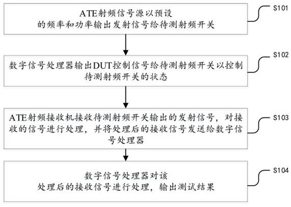
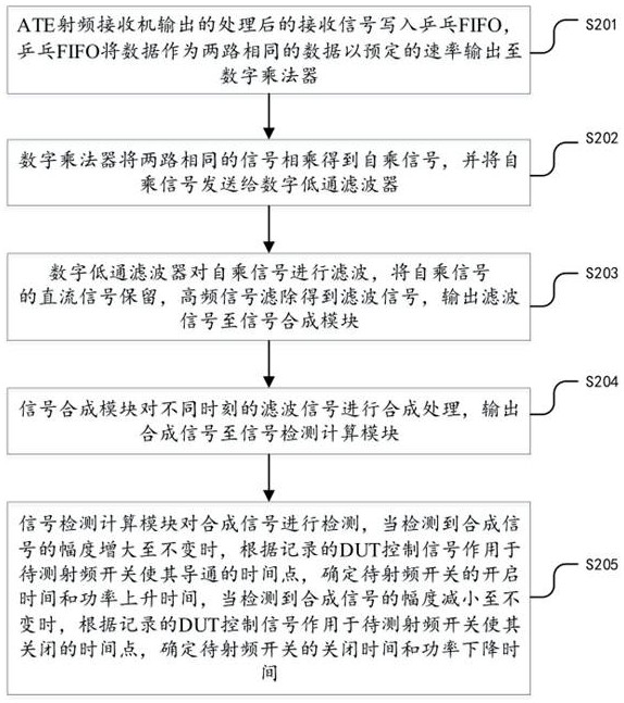
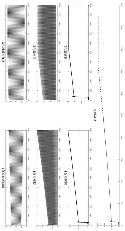
[0063] In order to make the object, technical solution and advantages of the present invention clearer, the present invention will be further described in detail below in conjunction with the accompanying drawings and embodiments. It should be understood that the specific embodiments described here are only used to explain the present invention, not to limit the present invention.

[0064] It should be noted that although the functional modules are divided in the system schematic diagram and the logical order is shown in the flow chart, in some cases, it can be executed in a different order than the module division in the system or the flow chart steps shown or described. The terms "first", "second" and the like in the specification and claims and the above drawings are used to distinguish similar objects, and not necessarily used to describe a specific sequence or sequence.

[0065] The embodiments of the present invention will be further described below in conjunction with ...


PUM


Abstract

The invention discloses a method and a system for testing response time of a radio frequency switch chip. The method comprises the steps that: an ATE radio frequency signal source outputs a transmitted signal to a to-be-tested radio frequency switch at preset frequency and power; a digital signal processor outputs a DUT control signal to the to-be-tested radio frequency switch to control the stateof the to-be-tested radio frequency switch; an ATE radio frequency receiver receives a transmitted signal output by the to-be-tested radio frequency switch, processes the received signal, and sends the processed received signal to a digital signal processor; and the digital signal processor processes the processed received signal and outputs a test result. The system comprises the digital signalprocessor, the ATE radio frequency signal source, the ATE radio frequency receiver and the to-be-tested radio frequency switch. According to the method and the system, digital domain processing is carried out on the basis of the signal receiver, the influence of the time response of a detector and the influence of the analysis bandwidth of an oscilloscope are avoided, the bandwidth of a processable signal is wide, the test rate of ATE equipment is improved, and the hardware complexity is reduced.

Description

technical field [0001] The invention relates to the technical field of switch testing, in particular to a method and system for testing the response time of a radio frequency switch chip. Background technique [0002] The time response of the RF switch is an important indicator of the RF switch chip, which can fully characterize its turn-on and turn-off speed, as well as the signal stabilization time. In the RF switching time response test, it is mainly divided into two categories, namely the switch response time, which is divided into on time (tON) and off time (tOFF), and the power response time, which is divided into power rise time (tRISE) and power fall time (tFALL). These tests are the detection of the control signal and the power value (envelope) of the input and output RF signals, which respectively characterize the turn-on and turn-off time and the signal stabilization time. [0003] Currently, there are two main methods for testing the time response of RF switch ...

Claims


Application Information

Patent Timeline
Patent Type & Authority Applications(China)
IPC IPC(8): G01R31/327G01R31/28
CPCG01R31/2822G01R31/2834G01R31/2882G01R31/327
Inventor 刘旭伟莫松安谷颜秋
Owner 佛山市联动科技股份有限公司
Why Eureka
Try Eureka