Rotating shaft conductive structure for rotary welding device

A conductive structure and welding device technology, applied in the direction of rolling contact bearings, rotating bearings, bearings, etc., can solve the problems of grounded rotors that are prone to heating and deformation, cable winding damage, and low work efficiency, so as to avoid the impact of shaft vibration, Ensures stable contact and improves welding quality

Active Publication Date: 2021-01-08
王俊霞
View PDF6 Cites 0 Cited by
  • Summary
  • Abstract
  • Description
  • Claims
  • Application Information

AI Technical Summary

Problems solved by technology

Although this method is simple, it is easy to cause damage to the cable winding, and the loss of the cable is very large
Another is to use ordinary grounded rotors, but the grounded rotors are prone to heat and deformation, and with the rotation of the workpiece, the grounded rotors will be stuck after working for a period of time and cannot rotate.
[0005] Therefore, if the method of directly fixing the ground wire on the workpiece for welding is labor-intensive, the work efficiency is low, and the service life of the cable is short.
If an ordinary grounded rotor is used, not only the quality of the product will be affected, but the high temperature will also pose a threat to the safety of production workers

Method used


Image

  • Rotating shaft conductive structure for rotary welding device
  • Rotating shaft conductive structure for rotary welding device
  • Rotating shaft conductive structure for rotary welding device

Examples


preparation example Construction

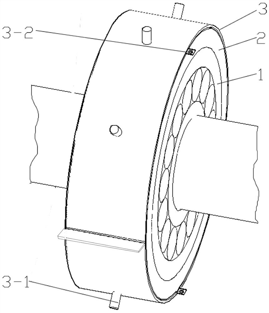
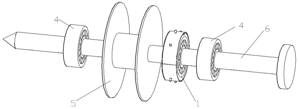
[0021] A rotating shaft conductive structure for a rotary welding device, the rotating shaft conductive structure is arranged at the rotating shaft 6 of the rotary welding device, the rotating shaft conductive structure includes a rolling bearing 1, and a conductive rubber sleeve 2 and a conductive copper sheet are arranged on the outer ring of the rolling bearing 1 3. The conductive rubber sleeve 2 is sandwiched between the outer ring of the rolling bearing 1 and the conductive copper sheet 3. The conductive copper sheet 3 is a ring structure composed of upper and lower semicircular arc-shaped sheets, and the conductive copper sheet 3 is set There is a conductive connector 3-2, and a mounting hole is stamped on the conductive copper sheet 3, and a positioning column 3-1 is installed at the mounting hole, and the conductive rubber sleeve 2 includes a tubular material layer, an adhesive layer and a metal layer in sequence from the inside to the outside. Mesh layer, metal powder ...

Embodiment 1

[0030] A rotating shaft conductive structure for a rotary welding device, the rotating shaft conductive structure is arranged at the rotating shaft 6 of the rotary welding device, the rotating shaft conductive structure includes a rolling bearing 1, and a conductive rubber sleeve 2 and a conductive copper sheet are arranged on the outer ring of the rolling bearing 1 3. The conductive rubber sleeve 2 is sandwiched between the outer ring of the rolling bearing 1 and the conductive copper sheet 3. The conductive copper sheet 3 is a ring structure composed of upper and lower semicircular arc-shaped sheets, and the conductive copper sheet 3 is set There is a conductive connector 3-2, and a mounting hole is stamped on the conductive copper sheet 3, and a positioning column 3-1 is installed at the mounting hole, and the conductive rubber sleeve 2 includes a tubular material layer, an adhesive layer and a metal layer in sequence from the inside to the outside. In the mesh layer, metal ...

Embodiment 2

[0034] On the basis of Embodiment 1, this embodiment mainly changes the specific parameters of the formulation and process of the conductive rubber sleeve 2, and the specific description is as follows:

[0035] The conductive rubber sleeve 2 is prepared by the following steps: metal powder and additives are put into the mixer according to the set ratio, and after being dispersed and stirred, the conductive material is obtained; the above-mentioned mixed silicone rubber material is passed through the extruder Extrude the material into a tubular shape, where the extrusion pressure is 4MPA, and the extrusion temperature is 185°C; mix and stir the adhesive layer raw materials according to a certain ratio, and evenly coat the mixed adhesive layer silica gel raw materials on the obtained in the previous step The inner and outer surfaces of the tubular material are set aside; the inner and outer surfaces of the tubular material layer obtained above are laid with metal mesh, and the la...


PUM


Abstract

The invention discloses a rotating shaft conductive structure for a rotary welding device. The rotating shaft conductive structure is arranged at a rotating shaft of the rotary welding device, and therotating shaft conductive structure comprises a rolling bearing; the outer ring of the rolling bearing is provided with a conductive rubber sleeve and a conductive copper sheet, and the conductive rubber sleeve is clamped between the outer ring of the rolling bearing and the conductive copper sheet; the conductive copper sheet is of an annular structure composed of an upper semi-arc-shaped sheetand a lower semi-arc-shaped sheet, a conductive connector is arranged on the conductive copper sheet, an installation hole is punched in the conductive copper sheet, a positioning column is installedat the installation hole, and the conductive rubber sleeve sequentially comprises a tubular material layer, a bonding layer and a metal net layer from inside to outside. According to the scheme, by reasonably designing the conductive structure of the rotary welding device, the rotary welding quality is guaranteed, and missing welding and missing welding are avoided.

Description

technical field [0001] The invention belongs to the technical field of welding equipment, and in particular relates to a rotating shaft conductive structure for a rotary welding device. Background technique [0002] As we all know, threaded sleeves are widely used in many fields as fixed connection parts. The processing of existing threaded sleeves is to connect two ends of a sleeve section with two nuts by welding. When using an electric welding machine to weld, the workpiece needs to be grounded. When the workpiece is rotated and welded, how to connect the workpiece to the ground wire through a wire is a problem that needs to be solved at present. [0003] Welding is called welding and welding. It is a method of joining metals by heating, high temperature or high pressure. Welding requires limbs to drive the welding device into contact with the workpiece. There are potential safety hazards in the welding process, and welding will occur if the workpiece is manually driven i...

Claims


Application Information

Patent Timeline
Patent Type & Authority Applications(China)
IPC IPC(8): H01R4/64C04B35/10C04B35/622C04B35/626F16C19/00F16C33/30F16C33/58F16F15/126
CPCH01R4/64C04B35/10C04B35/622C04B35/62655F16C19/00F16C33/30F16C33/581F16F15/126C04B2235/3409C04B2235/349C04B2235/449C04B2235/444C04B2235/445
Inventor 王俊霞
Owner 王俊霞
Why Eureka
Try Eureka