
Laminated battery cell production system

A production system and lamination technology, applied in electrochemical generators, circuits, electrical components, etc., can solve the problems of low lamination efficiency, large floor space, unfavorable lamination cell production and manufacturing, etc., and achieve lamination efficiency. High, small footprint, and the effect of improving lamination efficiency

Pending Publication Date: 2021-01-12
CONTEMPORARY AMPEREX TECH CO
View PDF0 Cites 1 Cited by
  • Summary
  • Abstract
  • Description
  • Claims
  • Application Information

AI Technical Summary

Problems solved by technology

[0003] In the traditional stacking equipment, the pole piece is first punched and shaped by the pole piece punching machine and installed on the material box, after filling a material box, the pole piece is transferred to the stacker, and the pole piece is stacked through the stacking platform. The stacking platform usually adopts a linear movement method to stack the pole pieces. Specifically, in the production process of the stacked cells, the stacking platform is first translated to the position where the positive pole piece is located, so as to stack the positive pole pieces. After the positive pole pieces are stacked, the lamination platform is moved to the position of the negative pole pieces in a straight line, and then the negative pole pieces are stacked. This kind of stacking method has defects such as low stacking efficiency and large floor space. It is not conducive to the production and manufacture of laminated cells

Method used


Image

  • Laminated battery cell production system
  • Laminated battery cell production system
  • Laminated battery cell production system

Examples


Embodiment Construction

[0047] Features and exemplary embodiments of various aspects of the invention will be described in detail below. In the following detailed description, numerous specific details are set forth in order to provide a thorough understanding of the present invention. It will be apparent, however, to one skilled in the art that the present invention may be practiced without some of these specific details. The following description of the embodiments is only to provide a better understanding of the present invention by showing examples of the present invention. In the drawings and the following description, at least some well-known structures and techniques have not been shown in order to avoid unnecessarily obscuring the present invention; and, for clarity, the dimensions of some structures may have been exaggerated. Furthermore, the features, structures, or characteristics described hereinafter may be combined in any suitable manner in one or more embodiments.

[0048] The orientat...


PUM


Abstract

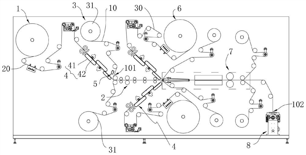
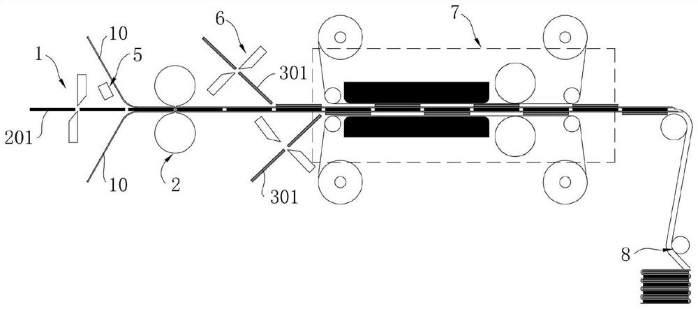
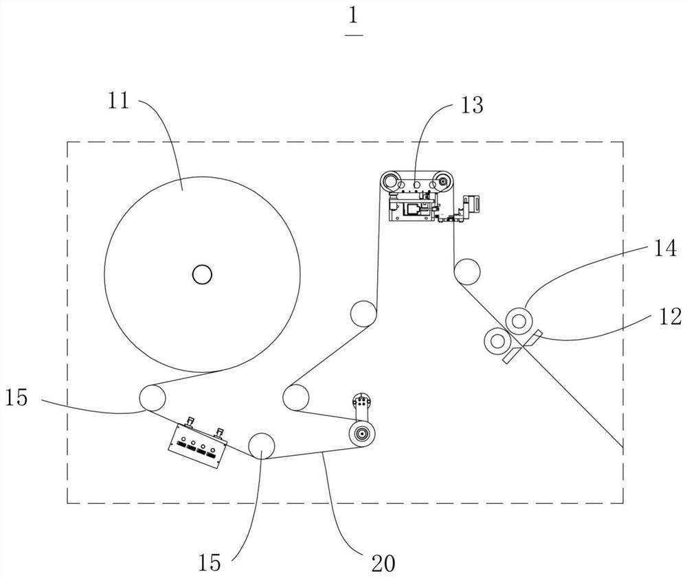
The invention relates to a laminated battery cell production system, which comprises an anode conveying mechanism capable of providing an anode unit with a predetermined size; an isolating membrane packaging mechanism arranged at the downstream of the anode conveying mechanism and used for clamping the anode unit between isolating membranes; a laminating mechanism capable of connecting with the isolating membrane and laminating the isolating membrane; an electrostaticizing mechanism which is arranged at the upstream of the isolating membrane packaging mechanism and can enable the isolating membrane to be electrified so as to adsorb the anode unit; a cathode conveying mechanism which is arranged at the upstream of the laminating mechanism and can provide a cathode unit with a preset size; and a cathode compounding mechanism which is arranged at the downstream of the cathode conveying mechanism, wherein the isolating membrane can penetrate through the cathode compounding mechanism to thelaminating mechanism, and the cathode compounding mechanism is used for connecting the cathode unit to the surface, far away from the anode unit, of the isolating membrane. According to the laminatedbattery cell production system provided by the embodiment of the invention, the laminating precision and efficiency can be improved, the occupied area is small, and production and manufacturing of battery cells are facilitated.

Description

technical field [0001] The invention relates to the technical field of energy storage production equipment, in particular to a production system for laminated batteries. Background technique [0002] At present, due to the advantages of high rate and high energy density of laminated batteries compared with wound batteries, and laminated batteries can also be made into various special-shaped batteries according to different needs, laminated batteries are generally used in the industry Make batteries. [0003] In the traditional stacking equipment, the pole piece is first punched and shaped by the pole piece punching machine and installed on the material box, after filling a material box, the pole piece is transferred to the stacker, and the pole piece is stacked through the stacking platform. The stacking platform usually adopts a linear movement method to stack the pole pieces. Specifically, in the production process of the stacked cells, the stacking platform is first tran...

Claims


Application Information

Patent Timeline
Patent Type & Authority Applications(China)
IPC IPC(8): H01M10/04H01M6/00
CPCH01M10/0404H01M6/005Y02P70/50
Inventor 廖如虎曾钢虞永生戴亚
Owner CONTEMPORARY AMPEREX TECH CO
Learn More