Drying control method of drying system

A drying control and drying system technology, applied in the field of clothing treatment, can solve the problems of high energy consumption and long drying time, and achieve the effects of improving applicability, improving drying effect, and reducing drying energy consumption

Active Publication Date: 2021-01-15
QINGDAO HAIER AIR CONDITIONER GENERAL CORP LTD +2
View PDF6 Cites 5 Cited by
  • Summary
  • Abstract
  • Description
  • Claims
  • Application Information

AI Technical Summary

Problems solved by technology

[0005] In order to solve at least one of the above-mentioned problems in the prior art, that is, in order to solve the problems of long drying time and high energy consumption in the existing drying control method, the present invention provides a drying control method of the drying system. The drying system includes: a refrigerant circulation circuit, the refrigerant circulation circuit includes a compressor, a condenser, a throttling element and an evaporator connected through a refrigerant pipe, and a water recei

Method used


Image

  • Drying control method of drying system
  • Drying control method of drying system
  • Drying control method of drying system

Examples


Embodiment 1

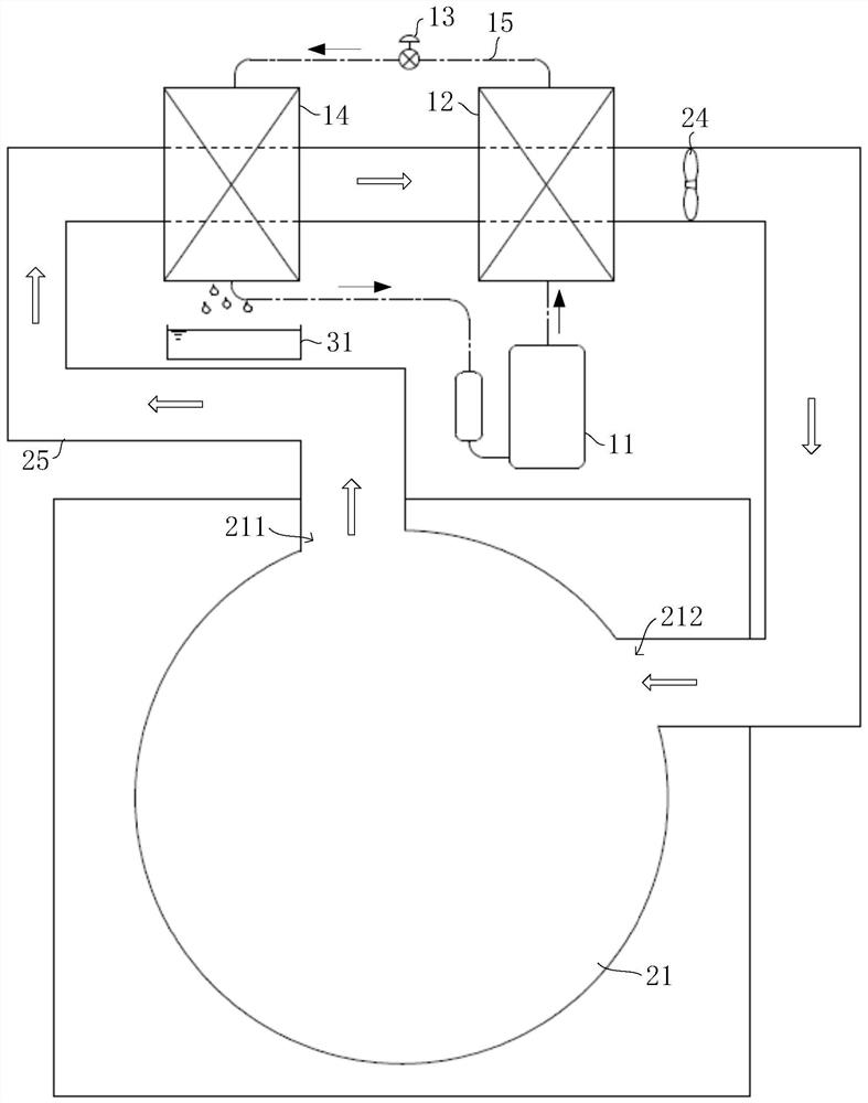
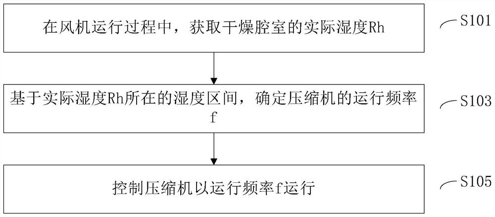
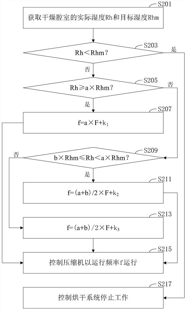
[0064] First refer to Figure 1-3 , to describe the first implementation manner of the drying control method of the present invention. in, figure 1 It is a system diagram of the drying system in the first embodiment of the present invention; figure 2 It is the main flowchart of the drying control method in the first embodiment of the present invention; image 3 It is a flowchart of a possible implementation of the drying control method in the first implementation of the present invention.

[0065] As mentioned in the background technology, in the existing drying system, as the moisture content of the clothes in the drying chamber gradually decreases, the relative humidity in the drying chamber is also getting smaller and smaller, and the air heated by the condenser is in the drying chamber The lowering range of the medium temperature also decreases, and the temperature of the air entering the evaporator and condenser continues to rise, which leads to the gradual weakening ...

Embodiment 2

[0086] Refer below Figure 4-5 , 9. Describe the second implementation manner of the drying control method of the present application. in, Figure 4 It is a system diagram of the drying system in the second embodiment of the present invention; Figure 5 It is the control flowchart of the water pump and the flow regulating valve in the second embodiment of the present invention; Figure 9 It is a structural diagram of a specific embodiment of the gas-liquid heat exchanger of the present invention.

[0087] Such as Figure 4 and Figure 9 As shown, in the second embodiment of the present application, on the basis of Example 1, the drying system further includes a gas-liquid heat exchanger 23 and a cooling circulation loop. The gas-liquid heat exchanger 23 has an air inlet 2311 , an air outlet 2312 , a liquid inlet 2313 and a liquid outlet 2314 , the air inlet 2311 communicates with the humid air outlet 211 , and the air outlet 2312 communicates with the inlet of the evapora...

Embodiment 3

[0104] Refer below Figure 6-7 , to describe the third implementation manner of the drying control method of the present application. in, image 3 It is a system diagram of the drying system in the second embodiment of the present invention. in, Figure 6 It is a system diagram of the drying system in the third embodiment of the present invention; Figure 7 It is the control flowchart of the first electric control valve and the second electric control valve in the third embodiment of the present invention.

[0105] Such as Figure 6As shown, in the third embodiment of the present application, on the basis of Embodiment 2, the water receiving tray 31 is further provided with a baffle 311, and the baffle 311 divides the water receiving tray 31 into a first part 312 and a second part 313 , the liquid inlet 2313 communicates with the first part 312, the liquid outlet 2314 communicates with the second part 313, and the first pipe section 151 and the second pipe section 152 con...


PUM


Abstract

The invention relates to the technical field of clothes treatment, in particular to a drying control method of a drying system. The problems that an existing drying control method is long in drying time and high in energy consumption are solved. To achieve the purpose, the drying control method comprises the steps that in the operation process of a draught fan, the actual humidity Rh of a drying cavity is obtained; based on the humidity interval where the actual humidity Rh belongs, the operation frequency f of a compressor is determined; and the compressor is controlled to operate at the operation frequency f, wherein the actual humidity Rh is in direct proportion to the operation frequency f. According to the drying control method of the drying system, the drying energy consumption can be considered while the drying efficiency is improved.

Description

technical field [0001] The invention relates to the technical field of clothes treatment, in particular to a drying control method of a drying system. Background technique [0002] In order to realize the rapid drying of clothes, the existing washing machine is equipped with a heat pump drying system. The heat pump drying system mainly includes refrigerant circulation and humid air circulation. Among them, the refrigerant cycle mainly includes a compressor, a condenser, a throttling device and an evaporator, and the wet air cycle includes an air duct and a fan. Set in the air duct. During operation, the humid air in the washing drum enters from one end of the air duct driven by the fan, and returns to the washing drum from the other end of the air duct after flowing through the evaporator and condenser in sequence. When the humid air passes through the evaporator, heat exchange occurs with the evaporator, the moisture in the humid air condenses into water droplets and the...

Claims


Application Information

Patent Timeline
IPC IPC(8): D06F58/38D06F58/20D06F103/34D06F105/26
CPCD06F58/38D06F58/206D06F2105/26D06F2103/34
Inventor 罗荣邦王飞崔灿侯永顺
Owner QINGDAO HAIER AIR CONDITIONER GENERAL CORP LTD
Why Eureka
Try Eureka