Auxiliary power generation system driven by stamping turbine and using method

A technology of auxiliary power generation and auxiliary generator, applied in the direction of electrical components, circuit devices, emergency power supply arrangements, etc., to improve the emergency power supply time, solve the mutual matching of the system, and solve the effects of insufficient power supply capacity

Active Publication Date: 2021-01-15
CHENGDU AIRCRAFT DESIGN INST OF AVIATION IND CORP OF CHINA
View PDF17 Cites 4 Cited by
  • Summary
  • Abstract
  • Description
  • Claims
  • Application Information

AI Technical Summary

Problems solved by technology

[0005]In order to solve the above problems, the present invention provides an auxiliary power generation system driven by a ram turbine and its usage method, which not only solves the problem of redundancy backup after the failure of the main bus bar , improve the reliability and safety, increase the emergency power supply time, realize the common work of the main bus bar and the auxiliary power generation system, and improve the entire power supply capacity in the task stage; through the comprehensive design of the controller, save resource expenses, reduce system costs, and improve System Compatibility

Method used


Image

  • Auxiliary power generation system driven by stamping turbine and using method

Examples


Embodiment Construction

[0024] This part is the embodiment of the present invention, which is used to explain and illustrate the technical solution of the present invention.

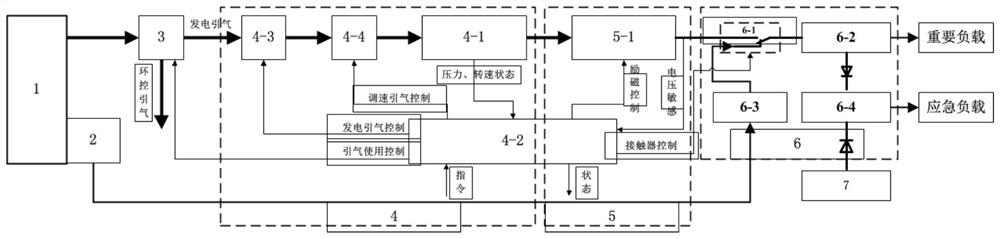
[0025] An auxiliary power generation system driven by a ram turbine, comprising an engine 1, a main generator 2, a bleed air valve 3, an auxiliary power unit 4, an auxiliary power generation system 5, and a power distribution system 6, the engine 1 is mechanically connected to the main generator 2, The current generated by the main generator 2 is transmitted to the power distribution system 6; the rear bleed air passage of the engine 1 is connected to the bleed air valve 3, and the bleed air valve 3 controls the distribution of the air flow to the environmental control system and the auxiliary power unit 4, which includes the turbine The power unit 4-1 and the integrated controller 4-2, the integrated controller 4-2 is connected to and controls the bleed air valve 3, the turbine power unit 4-1 is rotated by the bleed air of the ...


PUM


Abstract

The invention discloses an auxiliary power generation system driven by a stamping turbine. The auxiliary power generation system comprises an engine, a main power generator, an air-entraining valve, an auxiliary power device, an auxiliary power generation system body and a power distribution system, wherein a rear air-entraining channel of the engine is connected with the air-entraining valve, andthe air-entraining valve controls airflow to be distributed to an environment control system and the auxiliary power device; a comprehensive controller is connected with and controls the air-entraining valve; a turbine power device rotates through air entraining of the engine, and the turbine power device is in mechanical transmission connection with an auxiliary power generation device; and current generated by the auxiliary power generation system body is transmitted to the power distribution system. According to the auxiliary power generation system driven by the stamping turbine, an emergency function and an auxiliary function are integrated, the redundancy backup problem after a main bus bar breaks down is solved, reliability and safety are improved, and emergency power supply time is prolonged; the main bus bar and the auxiliary power generation system body work together, so the whole power supply capacity in the task stage is improved; and through the comprehensive design of acontroller, the resource overhead is saved, the system cost is reduced, and the system matching is improved.

Description

technical field [0001] The invention belongs to the technical field of aircraft power supply design, and relates to an aircraft auxiliary power generation system 5 system and a use method, in particular to a ram turbine driven auxiliary power generation system 5 system and a use method. Background technique [0002] With the continuous development of aviation technology, aircraft electrical equipment has increased sharply, which puts forward higher requirements for power supply system capacity, power supply quality and reliability. For long-endurance unmanned aerial vehicles, due to the extended emergency power supply time requirements, the emergency power supply The power demand has also increased significantly. In order to meet the requirements of aircraft development and the current situation of a single main bus bar with limited capacity, it is urgent to develop an auxiliary power generation system, which not only increases the total power capacity of the system, but also...

Claims


Application Information

Patent Timeline
Patent Type & Authority Applications(China)
IPC IPC(8): F02C6/00F02C7/32F02C7/047F02C9/16H02J9/08F01K23/02
CPCF02C6/00F02C7/32F02C7/047F02C9/16H02J9/08F01K23/02
Inventor 马中兵余灿陈春光刘松姜维东沈政斌
Owner CHENGDU AIRCRAFT DESIGN INST OF AVIATION IND CORP OF CHINA
Why Eureka
Try Eureka