Piston type flow regulating valve

A flow control valve and piston type technology, applied in the field of flow control valves, can solve the problems of increasing the diameter of the valve body, increasing the volume of the flow control valve, and the long distance of axial movement of the sliding sleeve, so as to reduce the diameter and drive the device. Compactness and improved sealing performance

Inactive Publication Date: 2021-01-15
陈艳艳
View PDF0 Cites 0 Cited by
  • Summary
  • Abstract
  • Description
  • Claims
  • Application Information

AI Technical Summary

Problems solved by technology

[0003] 1. The adjustment function of the flow control valve in the prior art is controlled by the movement of the piston-like sliding sleeve in the axial direction (water flow direction) in the valve cavity, thereby changing the throttle area of ​​the throttle hole on the first valve cylinder It is realized by the outlet valve area of ​​the water flow. Since the orifice holes on the first valve cylinder are distributed in multiple rows along the axial direction of the first valve cylinder, when the flow regulating valve is fully opened, the distance that the sliding sleeve moves in the axial direction is very long. In this way, the overall length of the flow regulating valve is longer, and the volume of the flow regulating valve is increased;
[0004] 2. The flow regulating valve in the prior art uses the sliding sleeve to move axially in the valve chamber to regulate the flow. There is a clearance fit between the sliding sleeve and the first valve barrel. When the flow regulating valve is in the closed state, the sealing performance is not good. it is good;
[0005] 3. The flow control valve in the prior art controls the valve stem to move up and down in the radial direction of the valve body through the driving device, and the helical rack on the valve stem cooperates with the helical rack on the valve sleeve to drive the valve sleeve along the axial direction of the valve body. Move to change the throttling area. Since the sliding sleeve moves from the closed position to the fully open position for a long distance, the valve stem moves along the valve body for a long distance, which not only increases the diameter of the valve body, but also increases the volume of the valve body. If it is too large, the overall size of the drive device will be larger and the cost will be higher

Method used


Image

  • Piston type flow regulating valve
  • Piston type flow regulating valve
  • Piston type flow regulating valve

Examples


Embodiment Construction

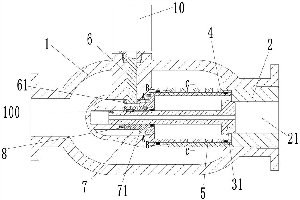
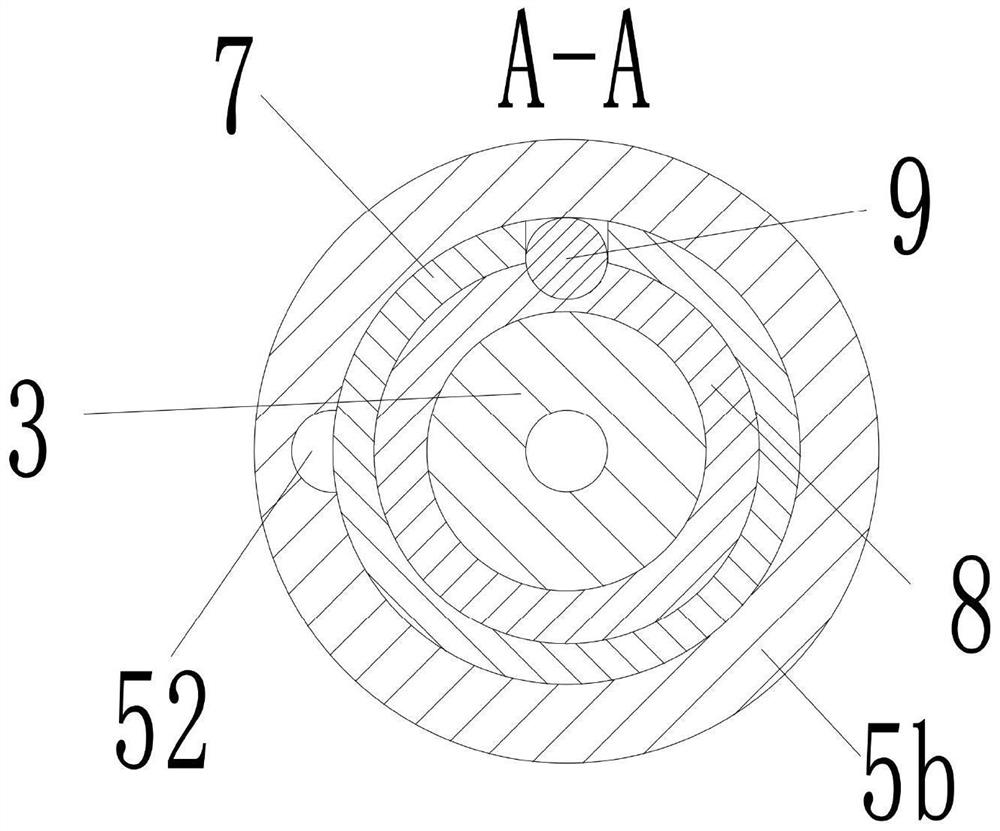
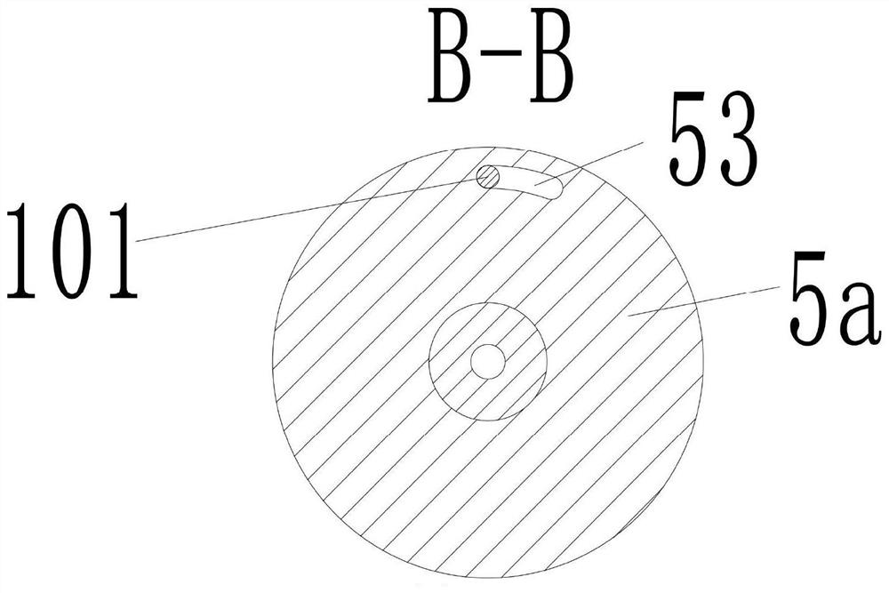
[0031] see Figure 1-13 As shown, the present invention provides a piston-type flow control valve, including a valve body 1, a valve chamber 1a is arranged inside the valve body 1, an inlet pipe 1b is arranged at the left end of the valve body 1, and an outlet pipe 1c is arranged at the right end ; The outlet pipe 1c is fixed with a valve block 2, and the valve block 2 is provided with a valve hole 21 along the left and right directions; the inner side wall of the valve cavity 1a is extended with a bump 1d, and the inside of the bump 1d A valve slot 1e with an open right end is provided, and a protruding shaft 1f extends rightward from the left end of the valve slot 1e. A shaft hole 1g with an opening at the right end is provided in the protruding shaft 1f, and a valve stem is provided in the shaft hole 1g. 3. The valve stem 3 is provided with a spiral groove 32 on the outside of one end extending into the shaft hole 1g, and the side wall of the shaft hole 1g is provided with ...


PUM


Abstract

The invention discloses a piston type flow regulating valve. The piston type flow regulating valve comprises a valve body, a valve cavity is formed in the valve body, an inlet pipe is arranged at theleft end of the valve body, an outlet pipe is arranged at the right end of the valve body, a valve block is fixedly arranged in the outlet pipe, a valve hole is formed in the valve block, a convex block is arranged on the inner side wall of the valve cavity in an extending mode, a valve groove is formed in the convex block, a convex shaft is arranged in the valve groove, a shaft hole is formed inthe convex shaft, a valve rod is arranged in the shaft hole, a spiral groove is formed in the outer side of the valve rod, a first convex column is arranged on the side wall of the shaft hole, a valveclack is arranged at the right end of the valve rod, a first valve cylinder is arranged in the valve cavity, a second valve cylinder is connected in the first valve cylinder in a rotating mode, a blind plate is arranged at the left end of a second valve cylinder, the valve rod is provided with a rotary drum, the outer side of the rotary drum is sleeved with a sleeve, a convex ring is arranged onthe left side of the blind plate in an extending mode, a driving assembly is arranged on the valve body, and a transmission assembly is arranged among the rotary drum, the sleeve and the convex ring.The piston type flow regulating valve has the advantages of being reliable in sealing and compact in size.

Description

technical field [0001] The invention belongs to the technical field of flow control valves, in particular to a piston type flow control valve. Background technique [0002] Due to its high adjustment accuracy, low cavitation, noise and vibration, good energy dissipation effect, ideal flow-opening curve, and easy automatic control, it has been widely used in many large water delivery projects. The main functions of the flow regulating valve are in three aspects: energy dissipation, flow regulation and emergency treatment. The first is the energy dissipation effect. During operation, the water flow passes through the flow regulating valve and collides with the outlet to dissipate energy. The kinetic energy of the water body is basically reduced to zero, so that the flow state of the water body in the downstream pipeline becomes more stable and the operation is safer. The flow regulating valve of the prior art has the following technical problems: [0003] 1. The adjustment f...

Claims


Application Information

Patent Timeline
Patent Type & Authority Applications(China)
IPC IPC(8): F16K5/04F16K1/38F16K31/04F16K31/53F16K31/50
CPCF16K1/38F16K5/0407F16K5/0414F16K5/0421F16K5/0442F16K31/043F16K31/047F16K31/50F16K31/535
Inventor 李来滨邵建国杜爱芝
Owner 陈艳艳
Why Eureka
Try Eureka