
Low-energy-consumption industrial microwave sintering equipment

A technology of industrial microwave and sintering equipment, which is applied in the direction of microwave heating, lighting and heating equipment, heating room maintenance, etc. It can solve problems such as labor-intensive, safety hazards, and slow material retrieving efficiency, so as to avoid burns, facilitate retrieving materials, The effect of convenient retrieving operation

Inactive Publication Date: 2021-01-15
娄底光华机械设备制造有限公司
View PDF5 Cites 0 Cited by
  • Summary
  • Abstract
  • Description
  • Claims
  • Application Information

AI Technical Summary

Problems solved by technology

[0003] The low-energy microwave sintering equipment in the prior art usually uses a crucible as a carrier for the material to be sintered. When the sintered material is taken out, it is usually necessary for the staff to wear heat-insulating gloves and use the tongs to take out the crucible. , this method not only consumes a certain amount of labor, but also has a slow retrieving efficiency, and there are certain potential safety hazards

Method used


Image

  • Low-energy-consumption industrial microwave sintering equipment
  • Low-energy-consumption industrial microwave sintering equipment
  • Low-energy-consumption industrial microwave sintering equipment

Examples


Embodiment Construction

[0024] The following will clearly and completely describe the technical solutions in the embodiments of the present invention with reference to the accompanying drawings in the embodiments of the present invention. Obviously, the described embodiments are only some, not all, embodiments of the present invention. Based on the embodiments of the present invention, all other embodiments obtained by persons of ordinary skill in the art without making creative efforts belong to the protection scope of the present invention.

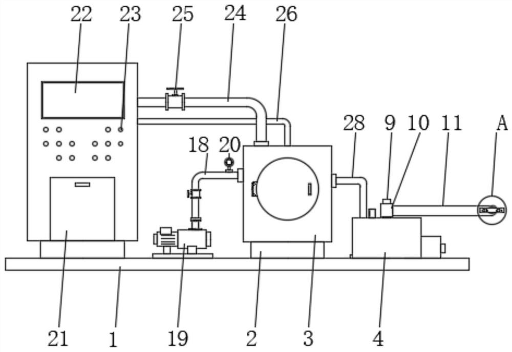
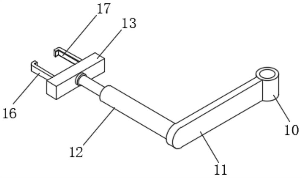
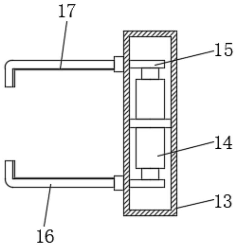
[0025] see Figure 1-7 , in the embodiment of the present invention, an industrial microwave sintering equipment with low energy consumption comprises a bottom plate 1, a sintering furnace base 2 is fixedly connected to the upper surface of the bottom plate 1, a sintering furnace 3 is fixedly connected to the top of the sintering furnace base 2, and the bottom plate 1 The upper surface of the drive box 4 is fixedly connected with the drive box 4, the inner bot...


PUM


Abstract

The invention discloses low-energy-consumption industrial microwave sintering equipment and belongs to the field of microwave sintering. The equipment comprises a bottom plate, the upper surface of the bottom plate is fixedly connected with a sintering furnace base, a sintering furnace is fixedly connected with the top of the sintering furnace base, a driving box is fixedly connected with the upper surface of the bottom plate, a driving motor is fixedly connected with the inner bottom wall of the driving box, the output end of the driving motor is sleeved with a first gear, one side of the first gear is engaged with a second gear, a rotating shaft is inserted into the inner wall of the second gear, a rotating column is fixedly connected to the top of the rotating shaft, and the outer wallof the rotating column is sleeved with a fixed cylinder. Through the arrangement of the driving motor, the first gear, the second gear, the rotating shaft, the rotating column, a supporting arm, an extensible air cylinder, a limiting barrel, an electric push rod and a clamping plate, the design is high in automation degree and operation is easy; the trouble of manually taking out a crucible is avoided, workers are prevented from making direct contact with the crucible, and the workers are prevented from being scalded; and therefore, the effects that the device is convenient in material takingand high in safety are achieved.

Description

technical field [0001] The invention relates to the field of microwave sintering, in particular to industrial microwave sintering equipment with low energy consumption. Background technique [0002] Microwave sintering is a method of using the special wave band of microwave to couple with the basic fine structure of the material to generate heat. The dielectric loss of the material makes the material as a whole heated to the sintering temperature to achieve densification. Microwave sintering is a new method of material sintering process , it has the characteristics of fast heating speed, high energy utilization rate, high heating efficiency, safety, sanitation and pollution-free, etc., and can improve the uniformity and yield of products, improve the microstructure and performance of sintered materials, and has become a popular technology in the field of material sintering. new research hotspot. [0003] The low-energy microwave sintering equipment in the prior art usually ...

Claims


Application Information

Patent Timeline
Patent Type & Authority Applications(China)
IPC IPC(8): F27B5/05F27B5/06F27B5/13F27B5/14F27B5/16F27B5/18F27D7/06F27D9/00H05B6/80
CPCF27B5/04F27B5/06F27B5/13F27B5/14F27B5/16F27B5/18F27D7/06F27D9/00H05B6/80F27B2005/062
Inventor 谢平光
Owner 娄底光华机械设备制造有限公司
Learn More