Method for adjusting LCD contrast through keys

A contrast and key technology, applied in the application field of monochrome LCD display in the field of automation, can solve the problems of complex production process, contrast jitter, and increase the failure rate of potentiometers.

Inactive Publication Date: 2021-01-19
临沂安迪电气有限公司
View PDF8 Cites 0 Cited by
  • Summary
  • Abstract
  • Description
  • Claims
  • Application Information

AI Technical Summary

Problems solved by technology

[0003] The traditional LCD display uses a potentiometer to adjust the contrast, which has the following disadvantages in the process of use: 1. Although the way of adjusting the contrast by the potentiometer is simple and easy to use, the production process is complicated. In order to facilitate the use of customers, the potentiometer for side adjustment is usually used , if the force is too large, it is easy to knock the potentiometer down. In order to prevent this from happening, the production process will increase the dispensing process to strengthen the support of the potentiometer, but at the same time increase the plug-in welding steps, which increases the production cost, and the traditional The failure rate is high when using the adjustment method. In the actual use environment, there may be high temperature, high humidity, etc., which will increase the failure rate of the potentiometer. The contrast jitter often occurs in the actual use process of the user, and the contrast becomes the maximum or minimum. For this reason, we propose a method to adjust the LCD contrast by pressing the button

Method used


Image

  • Method for adjusting LCD contrast through keys
  • Method for adjusting LCD contrast through keys

Examples


Embodiment 1

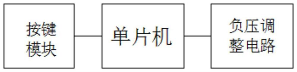
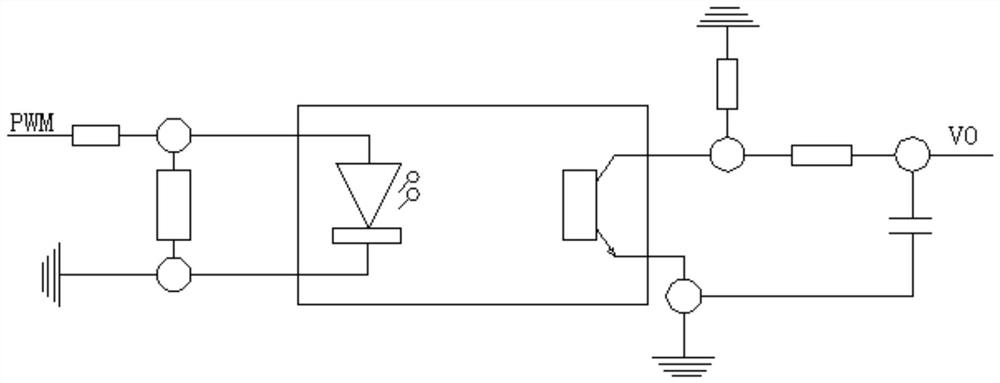
[0017] A method for adjusting LCD contrast through buttons, comprising a single-chip microcomputer, a button module, a negative pressure adjustment circuit, an optocoupler and an LCD display screen, one side of the single-chip microcomputer is installed with a current-limiting resistor and connected to the input terminal of the optocoupler through the current-limiting resistor, and the The output terminal of the optocoupler is equipped with a triode collector and an emitter, the collector of the triode at the output of the optocoupler pulls down the GND of the positive voltage, the emitter is externally connected with a negative voltage, and the current output terminal of the collector of the triode is equipped with a capacitor filter, The collector of the triode is connected to the LCD display screen after being filtered by a current-limiting resistor and a capacitor.

[0018] Preferably, the signal output terminal of the button module is connected to the signal input terminal...


PUM


Abstract

The invention discloses a method for adjusting LCD contrast through keys, and the method comprises a single-chip microcomputer, a key module, a negative voltage adjusting circuit, an optocoupler and an LCD display screen; a current-limiting resistor is installed on one side of the single-chip microcomputer and is connected with the input end of the optocoupler through the current-limiting resistor, the output end of the optocoupler is provided with a triode collector and an emitter, and a user operates the key module; after the single-chip microcomputer detects signals of the key module, the single-chip microcomputer controls the negative voltage adjusting circuit to adjust the negative voltage proportion, so contrast adjustment of an LCD is achieved, the input end of the optocoupler is connected with the bypass resistor in parallel, and the input voltage of the optocoupler is prevented from being too high. By adjusting the duty ratio output by the single-chip microcomputer, the conduction ratio of the optocoupler is adjusted, when the optocoupler is conducted, the filter capacitor is charged; when the optocoupler is not conducted, the filter capacitor is discharged. By matching reasonable resistance-capacitance parameters and signal parameters, the charging and discharging of the capacitor can be balanced, so the contrast ratio of the LCD is stably adjusted, the production process is optimized, the production cost is reduced, and potentiometer faults caused by potentiometer operation of a client are avoided at the same time.

Description

technical field [0001] The invention relates to the application technical field of a monochromatic LCD display screen in the field of automation, in particular to a method for adjusting the contrast of the LCD through keys. Background technique [0002] The LCD display is a liquid crystal display. The liquid crystal display is an active matrix liquid crystal display driven by thin film transistors. It mainly uses current to stimulate liquid crystal molecules to generate points, lines, and surfaces to form a picture with the back lamp tube. IPS, Both TFT and SLCD belong to the sub-categories of LCD. Under the action of electric field, the alignment direction of liquid crystal molecules is changed to change the light transmittance of the external light source to complete the electro-optic conversion, and then use the R, G, B three primary color signals to change the light transmittance of the external light source. With different excitations, through the red, green, and blue p...

Claims


Application Information

Patent Timeline
IPC IPC(8): G09G3/36
CPCG09G3/36G09G2320/0626
Inventor 王圣斌
Owner 临沂安迪电气有限公司
Why Eureka
Try Eureka