
Wire drawing device of ultra-micro wire for enameled wire production and wire drawing method of wire drawing device

An enameled wire and wire technology, used in the direction of reducing the size of conductors/cables, electrical components, circuits, etc., can solve problems such as poor adjustability, inability to ensure that the enameled wire transmission is in a straight state, and inability to detect differential speeds.

Inactive Publication Date: 2021-01-22
丁明弟
View PDF0 Cites 1 Cited by
  • Summary
  • Abstract
  • Description
  • Claims
  • Application Information

AI Technical Summary

Problems solved by technology

[0003] In the process of enameled wire processing, the wire drawing device is an indispensable equipment. Most of the wire drawing devices on the market have poor adjustability, cannot guarantee whether the transmission of the enameled wire is in a straight line state, and cannot be detected during the double wire drawing process. Whether there is a differential speed between the two, the inability to adjust the flexible interval of the device through the cylinder, and the problem that the electromagnetic field between the magnet and the carrier cannot be used to drive

Method used


Image

  • Wire drawing device of ultra-micro wire for enameled wire production and wire drawing method of wire drawing device
  • Wire drawing device of ultra-micro wire for enameled wire production and wire drawing method of wire drawing device
  • Wire drawing device of ultra-micro wire for enameled wire production and wire drawing method of wire drawing device

Examples


Embodiment 1

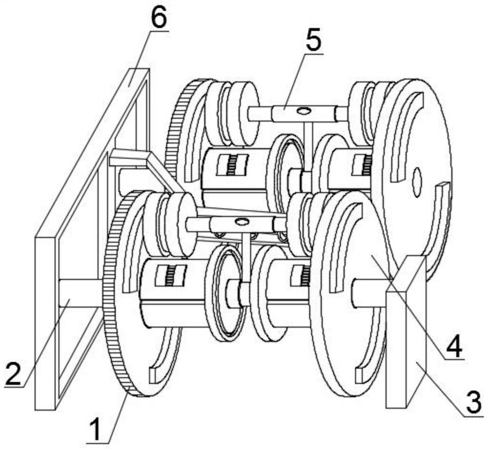
[0033] Such as figure 1 , 2 As shown in and 7, a wire drawing device and a wire drawing method for ultra-fine wire rods for enameled wire production, including a transmission mechanism 1, a drive mechanism 4 and a differential speed adjustment mechanism 5, the inner cavity of the transmission mechanism 1 and the drive mechanism 4 is provided with a fixed Cross bar 2, the other end of fixed cross bar 2 is fixedly connected with fixed vertical box 3, and the side end of assembling plate 16 is equipped with permanent magnet block 17, and permanent magnet block 17 is a kind of M shape member, and permanent magnet block 17 is embedded with Ring groove 42 cooperates, and the height that permanent magnet block 17 sets should be less than the depth that inlay ring groove 42 sets, is provided with differential speed adjustment mechanism 5 through between transmission mechanism 1 and driving mechanism 4, and transmission mechanism 1 and driving mechanism The mechanism 4 is installed on...

Embodiment 2

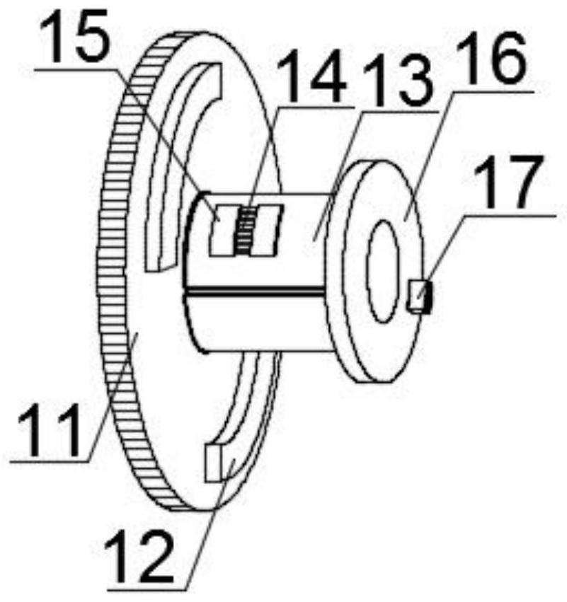
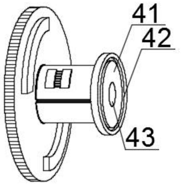
[0035] Such as figure 2 and 3As shown, a wire drawing device and a wire drawing method for ultra-fine wires for enameled wire production, the transmission mechanism 1 includes a rotating disk 11, an aluminum strip 12, a receiving horizontal cylinder 13, a limiting cavity 14, a limiting edge block 15, and an assembly plate 16 and permanent magnet block 17, the side end of rotating disc 11 is provided with aluminum strip 12 annularly, and the side end of rotating disc 11 is provided with accepting horizontal tube 13, and the outer end of accepting horizontal tube 13 is provided with limit cavity 14, and the limit cavity The two ends of 14 are provided with limited edge blocks 15, and the other end of the horizontal cylinder 13 is fixedly connected with the assembly disk 16. The drive mechanism 4 includes an assembly disk body 41, an embedded ring groove 42 and a through hole 43, and the assembly disk body 41 The annular array on the side end surface is provided with an embedde...

Embodiment 3

[0037] Such as Figure 4 , 5 Shown in and 6, a kind of enameled wire production uses the wire drawing device of ultra-fine wire rod and wire drawing method thereof, and differential speed adjustment mechanism 5 comprises hollow cylinder 51, threaded rod 52, friction roller 53, cylinder 54 and air vent 55, the hollow cylinder 51 The inner cavity is interspersed with a threaded rod 52, the two ends of the threaded rod 52 are provided with friction rollers 53, the bottom end of the hollow cylinder 51 is provided with a cylinder 54, and the top of the hollow cylinder 51 is provided with a vent hole 55, between the transmission mechanism 1 and the driving mechanism 4 In the process of non-contact electromagnetic transmission, the transmission mechanism 1 drives the driving mechanism 4 to move in the same direction, and at this time there will be a slight speed difference between the two, and the running speed of the transmission mechanism 1 will always be greater than or equal to t...


PUM


Abstract

The invention provides a wire drawing device of an ultra-micro wire for enameled wire production and and a wire drawing method of the wire drawing device, and relates to the field of the enameled wireproduction. The wire drawing device comprises a transmission mechanism, a driving mechanism and a differential adjusting mechanism, wherein the speed of the driving mechanism is reduced, the rotatingspeed of a friction roller on the right side is reduced, and as a result, the running balance force of a threaded rod cannot be maintained; the threaded rod connected with the friction roller on theright side triggers a vent valve arranged in an inner cavity of a hollow cylinder, air is conveyed to the inner cavity of the hollow cylinder by the vent valve through a vent hole, the air in the inner cavity of the hollow cylinder downwards enters an inner cavity of a built-in shell through an air inlet hole, and oxygen is conveyed to an inner cavity of a movable cross rod on the right side; through cooperation of a piston and an assembling contact shell, due to the principle that the farther the relative distance between the transmission mechanism and the driving mechanism is, the faster therotational driving speed is, when the running speed of the driving mechanism and the running speed of the transmission mechanism are adjusted to be consistent, the running balance force of the threaded rod is kept, and the vent valve arranged in the inner cavity of the hollow cylinder is closed to keep the distance between the transmission mechanism and the driving mechanism.

Description

technical field [0001] The invention relates to the field of enameled wire production, in particular to a wire-drawing device and a wire-drawing method for ultra-fine wires used in enameled wire production. Background technique [0002] Enameled wire refers to a metal wire that uses insulating varnish as an insulating coating and is used to wind electromagnetic coils, also known as electromagnetic wire. It is a main variety of winding wire, which is composed of conductor and insulating layer. After the bare wire is annealed and softened, it is painted and baked many times. However, it is not easy to produce products that meet both standard requirements and customer requirements. It is affected by factors such as raw material quality, process parameters, production equipment, and the environment. Therefore, the quality characteristics of various enameled wires are different, but they all have Mechanical properties, chemical properties, electrical properties, thermal properti...

Claims


Application Information

Patent Timeline
IPC IPC(8): B21C1/20B21C1/30H01B13/00
CPCB21C1/20B21C1/30H01B13/0006
Inventor 丁明弟
Owner 丁明弟
Learn More