
Steel wire rope symmetrical linkage chuck

A technology of steel wire rope and wire rope assembly, applied in the field of metal processing equipment, can solve the problems of slow automatic clamping or loosening of pipes, unfavorable equipment processing efficiency, poor equipment use effect, etc., to achieve fast installation and debugging, and reduce auxiliary clamping time. , Automatic centering and clamping, stable and reliable effect

Pending Publication Date: 2021-01-22
QIGO ELECTROMECHANICAL
View PDF0 Cites 0 Cited by
  • Summary
  • Abstract
  • Description
  • Claims
  • Application Information

AI Technical Summary

Problems solved by technology

The chucks of the existing structure are all composed of metal processing components, the overall mass is relatively large, the inertia is large during processing rotation, and the processing speed is relatively slow, resulting in increased energy consumption of the equipment
[0003] In addition, with the improvement of the automation of processing equipment, the market needs more and more automatic chucks that can automatically clamp pipes or rods, while the jaw drive mechanism (usually a screw drive structure) in the existing chucks is relatively weak. It is suitable for adding an automatic drive device. When the automatic drive device is directly added to the existing chuck, the automatic clamping or loosening of the pipe is slow, and the clamping time increases during the processing, which leads to poor use of the equipment and is not conducive to improving the processing efficiency of the equipment.

Method used


Image

  • Steel wire rope symmetrical linkage chuck
  • Steel wire rope symmetrical linkage chuck
  • Steel wire rope symmetrical linkage chuck

Examples


Embodiment Construction

[0026] Below in conjunction with accompanying drawing and specific embodiment the present invention is described in further detail:

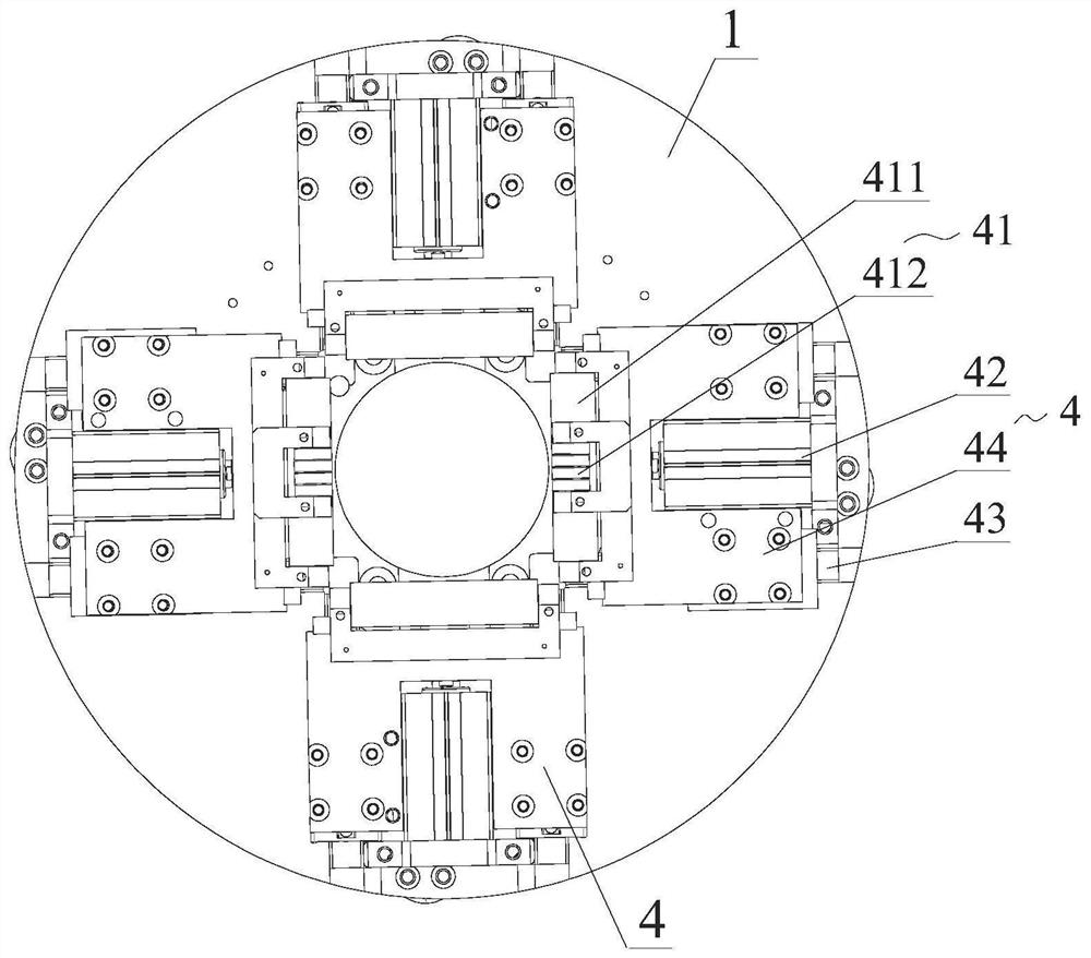
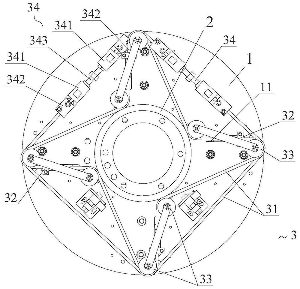
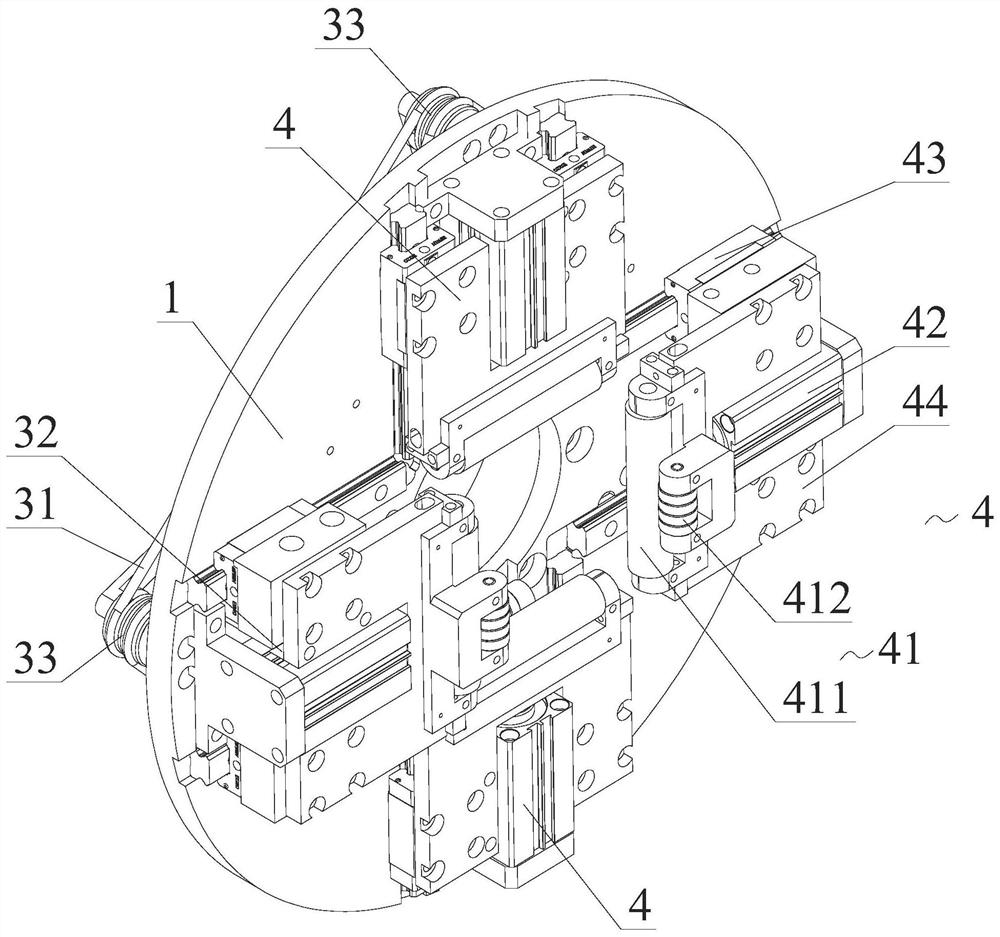
[0027] see Figure 1-4 As shown, a steel wire rope symmetrical linkage chuck includes a turntable body 1 and a positioning sleeve 2 supporting and fixing the turntable body 1. A wire rope assembly 3 is provided on the turntable body 1 on one side of the positioning sleeve 2. The turntable body The other side of 1 is provided with more than two groups of automatic jaw parts 4, and each group of automatic jaw parts 4 is provided with a guide pressure roller 41 and a driving cylinder 42, and the driving cylinder 42 drives the guide pressure roller 41 Reciprocating movement clamps or loosens the workpiece; the steel wire rope assembly 3 is provided with a tensioned steel wire rope 31, and a linkage 32 is fixed on the steel wire rope 31, and the guide pressure wheels in each group of the automatic jaw parts 4 41 are respectively connected with one o...


PUM


Abstract

The invention discloses a steel wire rope symmetrical linkage chuck which comprises a rotary disc body and a positioning sleeve for supporting and fixing the rotary disc body. A steel wire rope assembly is arranged at the position, at one side of the positioning sleeve, of the rotary disc body, two or more sets of automatic clamping jaw components are arranged at the other side of the rotary discbody, a guide pressing wheel and a driving air cylinder are arranged in each set of automatic clamping jaw component, and the driving cylinders drive the guide pressing wheels to move back and forth to clamp or loosen a workpiece; and tensioned steel wire ropes are arranged in the steel wire rope assembly, linkage pieces are fixed to the steel wire ropes, the guide pressing wheel in each set of automatic clamping jaw component is connected with one linkage piece, and the steel wire rope assembly is used for controlling the automatic clamping jaw components to achieve symmetrical and synchronous linkage clamping or loosening. According to the steel wire rope symmetrical linkage chuck, rapid and automatic concentric clamping can be achieved, the center of a clamped pipe or bar does not deviate, the clamped pipe or bar is firm and stable after automatic clamping, the chuck rotating precision is high, the overall inertia is small, the steel wire rope symmetrical linkage chuck is suitable for high-speed rotating machining, and the machining precision of the pipe or bar is guaranteed.

Description

technical field [0001] The invention relates to the technical field of metal processing equipment, in particular to a steel wire rope symmetrical linkage chuck. Background technique [0002] In the field of metal processing, especially when processing round pipes or rods, it is often necessary to use general or special chucks to hold pipes or rods. The existing chuck utilizes the radial movement of the movable jaws evenly distributed on the chuck body to clamp the workpiece. The chuck is generally composed of the chuck body, the movable jaws and the jaw driving mechanism. The chucks of the existing structure are all composed of metal processing components, and their overall mass is relatively large, the inertia is large during processing and rotation, and the processing speed is relatively slow, resulting in increased energy consumption of the equipment. [0003] In addition, with the improvement of the automation of processing equipment, the market needs more and more auto...

Claims


Application Information

Patent Timeline
Patent Type & Authority Applications(China)
IPC IPC(8): B23B31/16B23B31/24B23B31/30
CPCB23B31/16B23B31/24B23B31/30
Inventor 石森林欧亮魁杨荣焕
Owner QIGO ELECTROMECHANICAL
Learn More