Dust rod pressing machine for tobacco processing

The technology of a rod pressing machine and dust is applied in the direction of material forming presses, presses, manufacturing tools, etc., which can solve the problems of tobacco dust rods being difficult to loosen, and the extrusion effect of tobacco dust rods cannot be achieved, and achieves good molding effect, Good practical effect, reduce the effect of driving mechanism and related control mechanism

Inactive Publication Date: 2021-01-22
罗智
View PDF7 Cites 0 Cited by
  • Summary
  • Abstract
  • Description
  • Claims
  • Application Information

AI Technical Summary

Problems solved by technology

[0005] The purpose of the present invention is to provide a dust press machine for tobacco processing, aiming to solve the problem that the dust press machine for tobacco processing in the prior a

Method used


Image

  • Dust rod pressing machine for tobacco processing
  • Dust rod pressing machine for tobacco processing
  • Dust rod pressing machine for tobacco processing

Examples


Embodiment 1

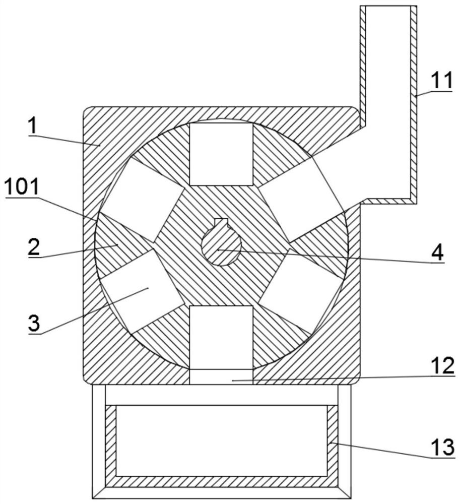
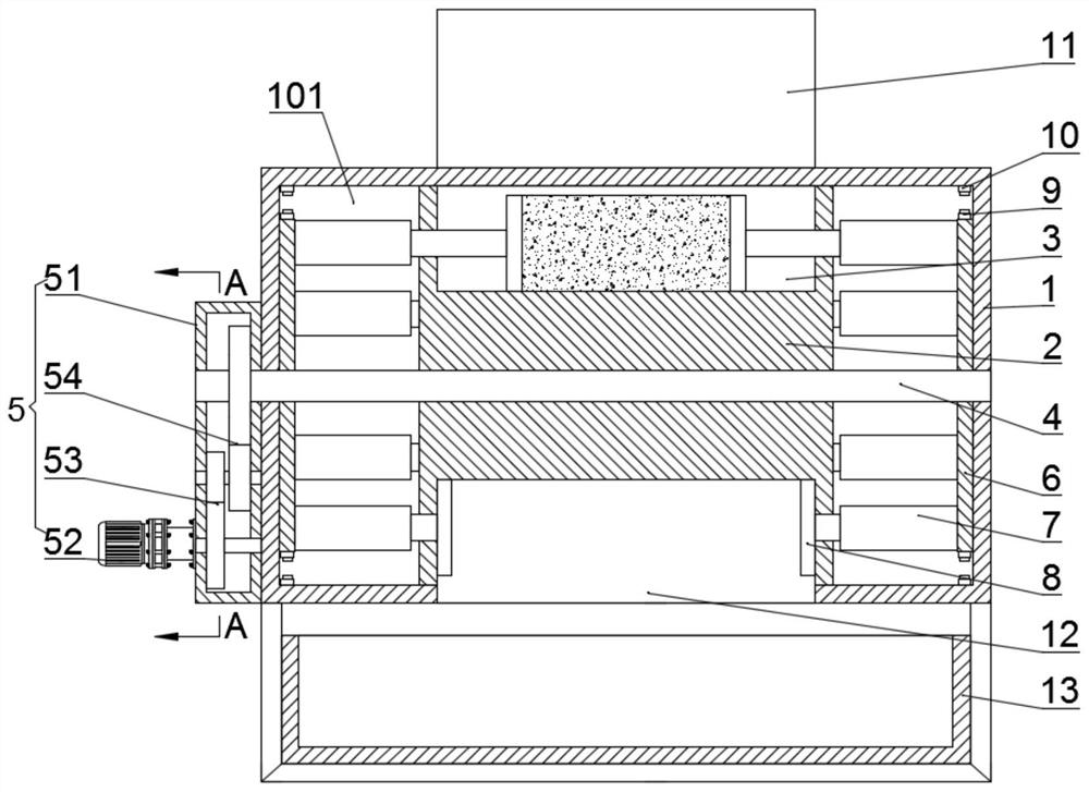
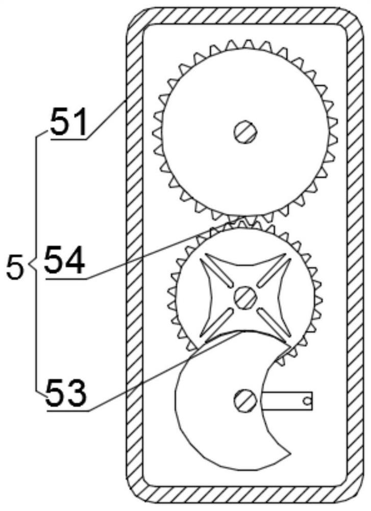
[0029] Such as Figure 1-4 As shown, a dust press machine for tobacco processing includes a housing 1, a cylindrical cavity 101 is opened inside the housing 1, and a cylindrical cavity 101 is arranged inside the cylindrical cavity 101. The rotating cylinder 2 arranged coaxially, and the circumferential surface of the rotating cylinder 2 is arranged in contact with the inner wall of the cylindrical cavity 101, and the installation hole of the rotating cylinder 2 is provided with a main shaft 4, and the main shaft 4 is connected with the housing The side wall of 1 is rotated and installed, and one end of the main shaft 4 is connected by a rotating drive mechanism 5. The circumferential surface of the rotating cylinder 2 is uniformly provided with a receiving groove 3, and the upper side of the side wall of the housing 1 is connected with an inlet The feed pipe 11, the lower side wall of the housing 1 is provided with a discharge port 12, when the rotating cylinder 2 rotates, the...

Embodiment 2

[0038] Such as Figure 1-4 As shown, a dust press machine for tobacco processing includes a housing 1, a cylindrical cavity 101 is opened inside the housing 1, and a cylindrical cavity 101 is arranged inside the cylindrical cavity 101. The rotating cylinder 2 arranged coaxially, and the circumferential surface of the rotating cylinder 2 is arranged in contact with the inner wall of the cylindrical cavity 101, and the installation hole of the rotating cylinder 2 is provided with a main shaft 4, and the main shaft 4 is connected with the housing The side wall of 1 is rotated and installed, and one end of the main shaft 4 is connected by a rotating drive mechanism 5. The circumferential surface of the rotating cylinder 2 is uniformly provided with a receiving groove 3, and the upper side of the side wall of the housing 1 is connected with an inlet The feed pipe 11, the lower side wall of the housing 1 is provided with a discharge port 12, when the rotating cylinder 2 rotates, the...


PUM


Abstract

The invention provides a dust rod pressing machine for tobacco processing, and relates to the technical field of tobacco processing. The dust rod pressing machine for tobacco processing comprises a shell, wherein a cylindrical cavity is formed in the shell, and a rotating cylinder coaxial with the cylindrical cavity is arranged in the cylindrical cavity. The circumferential surface of the rotatingcylinder is in contact with the inner wall of the cylindrical cavity, and a main shaft is arranged in a mounting hole of the rotating cylinder. The process from extrusion of tobacco dust by an extrusion head to discharge of tobacco dust through a discharge port is a pressure maintaining process, and the pressure maintaining process can pass through more stations, so that the pressure maintainingtime is longer, the pressure maintaining effect is ensured, the tobacco dust forming effect can be good, the tobacco dust is not prone to loosening, and in the pressure maintaining process, each timethe rotating cylinder rotates by one station, the working procedures of feeding, extruding and discharging are continuously carried out, so that the working efficiency is also improved under the condition of ensuring longer pressure maintaining time, and the practical effect is very good.

Description

technical field [0001] The invention relates to the technical field of tobacco processing, in particular to a dust pressing machine for tobacco processing. Background technique [0002] In order to facilitate the transportation of smoke and soil and reduce environmental pollution, a rod press machine is generally used to press powders such as smoke and soil into round rods. Existing soot pressing machines, whether hydraulic or mechanical, all adopt the form of extrusion. This type of bar pressing machine cannot handle dusty and sandy soot, such as the soot in a threshing and redrying factory. Due to the friction between soil and sand The force is large, and it is easy to cause the blockage of the raw material during the extrusion process, resulting in the shutdown of the equipment, and at the same time, the parts of the rod press are greatly worn by soil and sand. [0003] After searching, it is found that a Chinese patent with the authorized announcement number CN102990967...

Claims


Application Information

Patent Timeline
IPC IPC(8): B30B11/12B30B15/30B30B15/00
CPCB30B11/12B30B15/302B30B15/00
Inventor 罗智
Owner 罗智
Why Eureka
Try Eureka