Composite energetic thin film semiconductor bridge

A thin-film semiconductor and semiconductor technology, applied in the direction of offensive equipment, blasting barrels, weapon accessories, etc., can solve the problems of easy oxidation, high temperature resistance, instability, etc., and achieve the effect of facilitating energy conversion and strong ignition ability

Inactive Publication Date: 2021-01-22
PEKING UNIV
View PDF5 Cites 4 Cited by
  • Summary
  • Abstract
  • Description
  • Claims
  • Application Information

AI Technical Summary

Problems solved by technology

But the H-type bridge has no heat accumulation, and the ignition effect is average
In addition, the composite reaction film that is currently researched t

Method used


Image

  • Composite energetic thin film semiconductor bridge
  • Composite energetic thin film semiconductor bridge

Examples


Embodiment

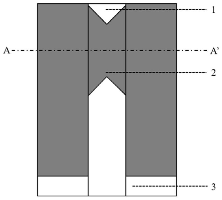
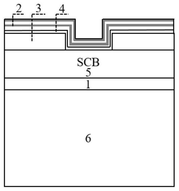
[0028] A compound energetic thin film semiconductor bridge, including a single crystal silicon substrate, SiO on the single crystal silicon substrate 2 Insulation layer, on SiO 2 Silicon ignition bridge region and aluminum electrode above thermal insulation layer, SiO over silicon ignition bridge region and aluminum electrode 2 insulating layer and sits on the SiO 2 The composite energetic thin film layer above the insulating layer, the material of the composite energetic thin film layer is B and Ti, and the thickness of the composite energetic thin film layer is 1 μm.

[0029] The preparation method of the above composite energetic thin film semiconductor bridge comprises the following steps:

[0030] Step 1, sputtering a 1 μm thick Al metal layer on the n-type semiconductor bridge substrate, and etching to form Al metal electrodes after photolithography.

[0031] Step 2, coating the substrate with the Al electrode obtained in step 1 with photoresist, pre-baking, alignment...


PUM

PropertyMeasurementUnit
Thicknessaaaaaaaaaa
Thicknessaaaaaaaaaa

Abstract

The invention relates to a composite energetic thin film semiconductor bridge which comprises a substrate, a heat insulation layer located on the upper surface of the substrate, a semiconductor bridgearea located on the upper surface of the heat insulation layer, electrodes located at the two ends of the bridge area, an insulating layer located on the upper surface of the bridge area and a composite energetic thin film layer located on the upper surface of the insulating layer. The composite energetic thin film layer is deposited on the surface of the insulating layer through magnetron sputtering. Compared with a traditional semiconductor bridge, the composite energetic thin film semiconductor bridge provided by the invention has the advantages that the composite energetic thin film layerformed by magnetron sputtering deposition replaces a first-stage manual detonation powder coating of the traditional semiconductor bridge, so that the composite energetic thin film semiconductor bridge is more controllable and safer; in terms of energy, the mass energy density of a B/Ti material selected by the invention is higher than the mass energy density of a common composite energetic thinfilm, so that energy conversion is better facilitated, the ignition capacity is high, and meanwhile, isolated ignition can be achieved; and a certain gap cavity is formed between a medicament and an energetic bridge, and a micro-security system based on MEMS is achieved in an ignition channel of the cavity, so that intelligence is achieved.

Description

technical field [0001] The invention belongs to the field of MEMS pyrotechnic igniters, in particular to a composite energetic thin film semiconductor bridge. Background technique [0002] Explosives are a general term for one-time use components and devices that are equipped with explosives and burn or explode after being stimulated by the outside to ignite gunpowder, detonate explosives or perform mechanical work. Bridge pyrotechnics are the most widely used pyrotechnics, which are divided into bridge wire type and bridge membrane type. [0003] With the combination of bridge-type pyrotechnic products and MEMS technology, the bridge-membrane ignition bridge has the characteristics of batch production, micro-integration, high safety, and low cost. According to the material of the bridge-membrane ignition bridge, it can be divided into metal membrane bridge, semiconductor membrane bridge, and composite energetic thin-film bridge. Among them, the composite energetic thin-fil...

Claims


Application Information

Patent Timeline
IPC IPC(8): F42B3/13
CPCF42B3/13
Inventor 张威邓有杞张良
Owner PEKING UNIV
Why Eureka
Try Eureka