Simultaneous localization and mapping method based on vision and laser radar

A lidar and map construction technology, applied in image enhancement, image analysis, image data processing and other directions, can solve the problems of motion distortion, easy degradation, lack of universality, etc., to achieve the effect of eliminating accumulated errors

Inactive Publication Date: 2021-01-22
ZHEJIANG UNIV
View PDF2 Cites 45 Cited by
  • Summary
  • Abstract
  • Description
  • Claims
  • Application Information

AI Technical Summary

Problems solved by technology

In addition, it also has a strong prior that point cloud information must contain a level of open road information, so this is more like a solution for specific road scenarios, not very universal
[0009] IMLS-SLAM is another pure laser vision positioning solution. It uses an implicit moving least squares (Implicit Moving Least Squares, IMLS) to represent the surface, and registers the feature points with the surface by screening features to achieve It achieves high positioning accuracy, but its shortcomings are also quite obvious. Due to the large amount of calculation, it cannot achieve real-time positioning, and it can generally be used for offline mapping.
[0010] Lidar also has some inherent disadvantages. For example, ordinary rotating LiDAR usually has motion distortion problems when it is in motion. The commonly used improved ICP method encounters repetitive structural scenes (such as moving in narrow and lengthy corridors) or lacks structure. The scene of information is easy to degrade, and there is still no efficient and robust solution for the loop detection of point cloud structure information, so that laser SLAM and visual SLAM cannot be directly combined

Method used


Image

  • Simultaneous localization and mapping method based on vision and laser radar
  • Simultaneous localization and mapping method based on vision and laser radar
  • Simultaneous localization and mapping method based on vision and laser radar

Examples


Embodiment

[0174] In order to further demonstrate the implementation effect of the present invention, this embodiment adopts KITTI's partially undistorted raw data in the rawdata data set, and selects 10 of the first 11 sequences (00-10) in KITTI as experimental data (sequence 03 and The corresponding raw point cloud data was not found from rawdata).

[0175] Evaluation indicators:

[0176] According to different positioning requirements, this embodiment uses relative error and absolute error to evaluate the level of positioning accuracy respectively.

[0177] The relative error evaluation takes each pose as the starting frame, and takes 8 poses of 100 meters, 200 meters, 300 meters ... 800 meters, and then compares these poses with the real value poses calculated by the same method , divide the error by the actual length of each segment, and calculate the average rotation error R (unit: degree / 100 meters) and translation error t (unit: %). The relative error evaluation avoids the cumu...


PUM


Abstract

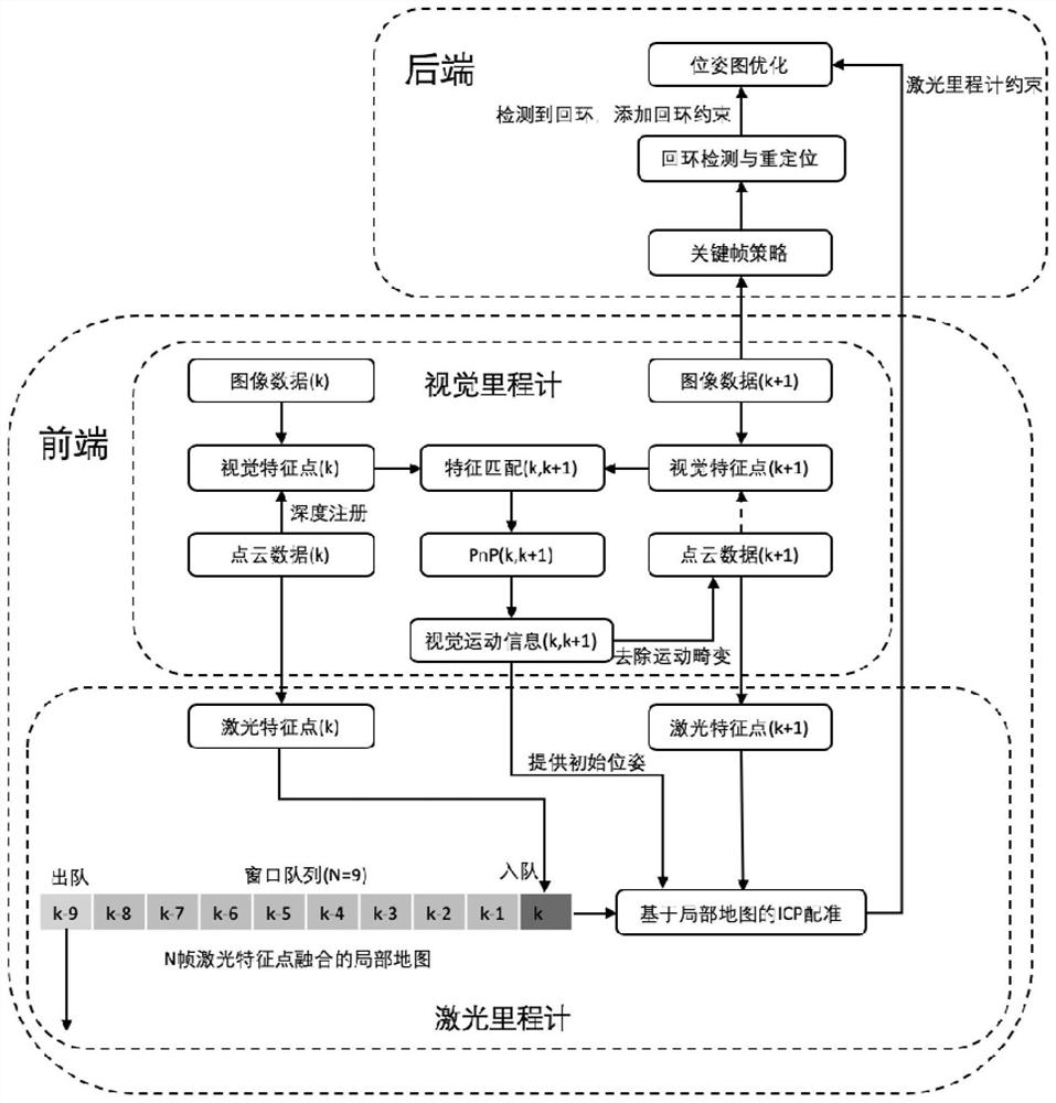
The invention discloses a simultaneous localization and mapping method based on vision and laser radar, and belongs to the field of SLAM. According to the method, the laser odometer and the visual odometer are operated at the same time, the visual odometer can assist the laser point cloud in better removing motion distortion, and meanwhile the point cloud with motion distortion removed can be projected to the image to serve as depth information for motion calculation of the next frame. After the laser odometer obtains a good initial value, the laser odometer is prevented from falling into a degradation scene due to the defects of a single sensor, and the odometer achieves higher positioning precision due to the addition of visual information. A loop detection and repositioning module is achieved through a visual word bag, and a complete visual laser SLAM system is formed; after loop is detected, the system performs pose graph optimization according to loop constraints, accumulated errors after long-time movement are eliminated to a certain extent, and high-precision positioning and point cloud map construction can be completed in a complex environment.

Description

technical field [0001] The invention relates to the field of simultaneous localization and map construction (SLAM), in particular to a simultaneous localization and map construction method based on vision and laser radar. Background technique [0002] With the rise of the concept of artificial intelligence and the maturity of computer vision-related technologies, unmanned equipment and robotics have received more and more attention. Among them, Simultaneous Localization and Mapping (SLAM) is an indispensable module in robot-related technologies. According to the different sensors used, SLAM technology can be mainly divided into camera-based visual SLAM and laser SLAM based on LiDAR (Light Detection and Ranging, LiDAR), in which visual SLAM can be subdivided into monocular SLAM, binocular SLAM and RGBD- SLAM, laser SLAM can be divided into 2D laser SLAM based on single-line lidar and 3D laser SLAM based on multi-line lidar. [0003] Visual SLAM is a low-cost solution that i...

Claims


Application Information

Patent Timeline
Patent Type & Authority Applications(China)
IPC IPC(8): G06T11/20G06T11/00G06T5/30G06T7/73G01S17/06G01S17/86G01S17/89
CPCG06T11/206G06T11/006G06T5/30G06T7/73G01S17/06G01S17/86G01S17/89G06T2207/10044G06T2207/10028
Inventor 章国锋鲍虎军王宇伟
Owner ZHEJIANG UNIV
Why Eureka
Try Eureka