Mounting and positioning structure of motor Hall circuit board

A technology for positioning structures and circuit boards, which is applied in the directions of electromechanical devices, structural connections, electrical components, etc., can solve the problems of cumbersome installation process, large position error and error of Hall relative to the circuit board, and achieves optimized current commutation structure without difficulty. Bending deformation, the effect of ensuring accuracy

Pending Publication Date: 2021-01-22
AIKEMA ELECTRIC DRIVE SYST (SUZHOU) CO LTD
View PDF2 Cites 1 Cited by
  • Summary
  • Abstract
  • Description
  • Claims
  • Application Information

AI Technical Summary

Problems solved by technology

But the traditional brushless Hall structure has natural disadvantages
In the current commutation structure using Hall detection, it is necessary to accurately sense the position of the magnetic steel through the Hall to perform commutation. When Hall senses the position of the magnets, it is necessary to sense multiple pairs of magnets when the rotor rotates one revolution, so that when the Hall position is not accurate enough relative to the position of the stator rotor, the error will increase in corresponding multiples according to the logarithm of the magnets used in the rotor
For example, in a motor using eight pairs of magnets, every degree of error of Hall relative to the axis of the stator and rotor will cause an error of more than 8 degrees between the rotation of the magnets and the current commutation
The original problems of the Hall motor, such as the vibration problem when the motor is running; the noise problem of resonance; the energy loss problem when the motor is working, will increase geometrically with the error of the Hall position.
This problem greatly limits the development of brushless motors
The traditional Hall structure is often directly installed inside the motor casing by welding. This Hall structure not only requires very high machining accuracy, but also has cumbersome installation procedures, high design and assembly costs, and requires pre-installation during motor assembly. There is a large assembly space and heat dissipation space, which makes it difficult to make the traditional motor structure smaller and more compact. In the traditional structure, the Hall element installed in the stator is extremely easy to be burned out.
These greatly limit the usage scenarios of the motor
[0003] In patents with CN 203233292 U and CN 203233293 U, respectively, a motor Hall plate installation structure and a motor Hall element installation structure are disclosed. In these two patents, although Hall Although the structure of the motor used on the board effectively reduces the volume of the motor, so that the Hall can be used as an assembly in the motor structure, but when the Hall is used in this structure, the Hall elements need to be attached to the circuit board through the Hall seat. Above, the circuit board is assembled on the wrapped stator seat inside the motor. At this time, Hall needs to be positioned through the structure of the stator seat, and the stator seat must be connected to the stator through other structures. At this time, the change of Hall and the measured The magnetic flux accommodates the tolerances of the various components inside the motor, and large tolerance changes may occur during assembly, so the position of the Hall attached to the stator seat through the circuit board is not accurate enough relative to the position of the moving magnetic parts that need to be measured. At the same time, because the assembly of the Hall needs to be welded by metal claws, once the metal claws are deformed, this will cause a large position error of the Hall relative to the circuit board. The seat is assembled on the circuit board, so it is difficult to ensure the relative position accuracy between each Hall, and the separate assembly also greatly increases the cost of the overall processing of the Hall board
All of the above problems make the Hall position of the Hall plate relative to the stator and rotor inaccurate, and the cost of using this structure on the motor is also relatively high

Method used


Image

  • Mounting and positioning structure of motor Hall circuit board
  • Mounting and positioning structure of motor Hall circuit board
  • Mounting and positioning structure of motor Hall circuit board

Examples


Embodiment Construction

[0025] Below in conjunction with embodiment the present invention is further described:

[0026] The directional words used in this patent, the positional relationship is based on the orientation or positional relationship shown in the drawings, only for the convenience of describing the application and simplifying the description, rather than indicating or implying that the referred device or element must have Certain orientations, constructed and operative in certain orientations, therefore should not be construed as limitations on the present application.

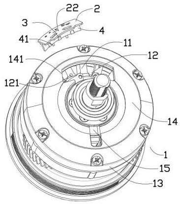
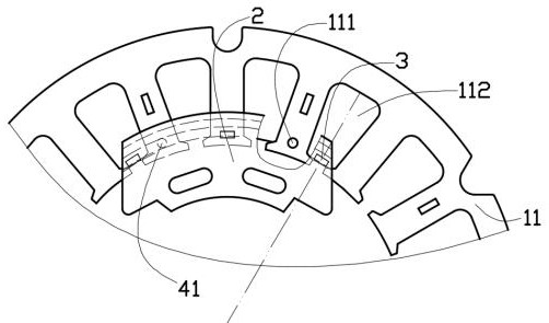
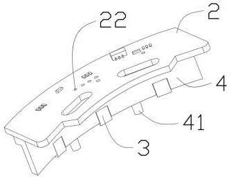
[0027] Such as figure 1 , figure 2 , image 3 and Figure 4As shown, in this embodiment, the installation and positioning structure of the Hall circuit board of the motor is mainly used in the motor 1, the stator 11 and the rotor 12 of the motor 1 are coaxially rotatable assembled on the stator seat 13, and the stator 11 and one side of the rotor 12 are designed with an inner cover 14 fixedly assembled with the stat...


PUM


Abstract

The invention provides a mounting and positioning structure of a motor Hall circuit board, which is used in a motor, a stator and a rotor of the motor are coaxially and rotatably assembled on a statorseat, an inner cover fixedly assembled with the stator seat is designed on one side of the stator and one side of the rotor, and a circuit board perpendicular to the axis of the stator and the axis of the rotor is assembled on the inner cover. More than two Halls extending to the position of a rotor magnetic block are assembled on the circuit board, the circuit board and the Halls are integrallyconnected through a fixing plate, the fixing plate is an arc-shaped panel perpendicular to the circuit board, and metal claws of the Halls penetrate through the end of the fixing plate to be welded with the electric connecting holes. More than two vertical positioning holes are machined in the side, close to the circuit board, of the stator, and positioning protrusions assembled with the positioning holes in a limited mode are machined on the side, away from the circuit board, of the fixing plate. The structure greatly optimizes the traditional current commutation structure, so that the current commutation of the stator is more accurate relative to the actual position judgment of the rotor.

Description

technical field [0001] The invention belongs to the technical field of brushless motor current commutation, and in particular relates to an installation and positioning structure of a Hall circuit board of a motor. Background technique [0002] During the working process of the motor, it is necessary to input an alternating current in the stator coil to generate an alternating magnetic field, thereby driving the rotor with magnetic steel to rotate. The brushless motor uses electromagnetic and electronic components such as Hall to replace the traditional mechanical brush structure for direct current. The current commutation operation makes the motor wear-free during operation, the failure rate is low, and the service life is longer. At the same time, the no-load current is small, the overall volume of the motor is smaller, and the efficiency is high. But the traditional brushless Hall structure has natural disadvantages. In the current commutation structure using Hall dete...

Claims


Application Information

Patent Timeline
Patent Type & Authority Applications(China)
IPC IPC(8): H02K11/215H02K29/08H02K5/22
CPCH02K5/225H02K29/08H02K2211/03H02K11/215
Inventor 沈国栋
Owner AIKEMA ELECTRIC DRIVE SYST (SUZHOU) CO LTD
Why Eureka
Try Eureka