Full-automatic hydraulic automatic tensioning device for conveying belt

A technology of automatic tensioning device and conveying device, applied in the field of conveying machinery, can solve the problems of affecting transmission efficiency, prone to slack, increasing frictional resistance, etc., and achieve the effect of improving transmission efficiency, improving work efficiency, and eliminating the need for deceleration devices.

Inactive Publication Date: 2021-01-26
浙江拓邦液压科技有限公司
View PDF0 Cites 0 Cited by
  • Summary
  • Abstract
  • Description
  • Claims
  • Application Information

AI Technical Summary

Problems solved by technology

[0003] The current belt conveyors are widely used in coal mines, metallurgical mines and other industries. During the long-term use of the conveyor belt, due to the difference in load and tension between starting and normal operation, the belt conveyor is prone to slack. The frictional resistance is increased, so that the operation of the belt cannot be stable, and the efficiency is relatively low
At the same time, the belt is prone to deviation during operation, which greatly affects the transmission efficiency, and even leads to the failure of normal transmission work

Method used


Image

  • Full-automatic hydraulic automatic tensioning device for conveying belt
  • Full-automatic hydraulic automatic tensioning device for conveying belt
  • Full-automatic hydraulic automatic tensioning device for conveying belt

Examples


Embodiment Construction

[0027] The following will clearly and completely describe the technical solutions in the embodiments of the present invention with reference to the accompanying drawings in the embodiments of the present invention. Obviously, the described embodiments are only some, not all, embodiments of the present invention. Based on the embodiments of the present invention, all other embodiments obtained by persons of ordinary skill in the art without making creative efforts belong to the protection scope of the present invention.

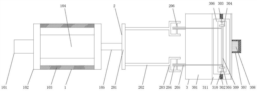
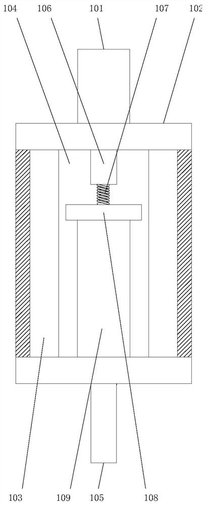
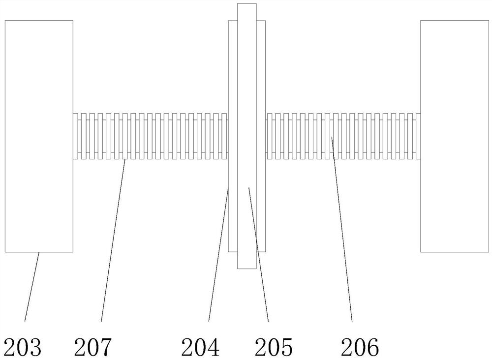
[0028] see Figure 1-5 , the present invention provides a technical solution: a fully automatic conveyor belt hydraulic automatic tensioning device, including a hydraulic cylinder device 1, a conveying device 2 and a tensioning device 3, and the right side of the hydraulic cylinder device 1 is movably installed with a conveying device 2, A tensioning device 3 is movably installed on the right side of the front of the conveying device 2 .

[0029] The hydrauli...


PUM


Abstract

The invention discloses a full-automatic hydraulic automatic tensioning device for a conveying belt. A hydraulic oil cylinder device, a conveying device and a tensioning device body are included, theconveying device is movably installed on the right side of the front face of the hydraulic oil cylinder device, and the tensioning device body is movably installed on the right side of the front faceof the conveying device. The hydraulic oil cylinder device is composed of a pressing rod, a gland, a supporting rod, a cylinder barrel, a hydraulic driving rod, a piston body, an elastic spring, a fixing piece and a supporting bridge, the pressing rod is movably installed in the center of the left side of the front face of the hydraulic oil cylinder device, the right side of the front face of thepressing rod is movably connected with the gland, and the cylinder barrel is movably arranged at the center of the right side of the front face of the gland. According to the full-automatic hydraulicautomatic tensioning device for the conveying belt, a driving motor is started, a sliding groove formed in the right side of the surface of a fixed base is tensioned, extension springs movably installed at the two ends of the front face of the sliding groove horizontally move, threads arranged on the front faces of sliding rods are matched with inner shafts arranged on the inner sides of the frontfaces of rotating wheels, the inner shafts are rotationally connected with the sliding rods, the automatic tensioning technology of the device is effectively carried out, and the conveying efficiencyis improved.

Description

technical field [0001] The invention relates to the technical field of conveying machinery, in particular to a fully automatic hydraulic automatic tensioning device for a conveying belt. Background technique [0002] The belt conveyor is a continuous-action transportation equipment in which the conveyor belt doubles as a traction mechanism and a load-carrying mechanism. It has been widely used in coal mines above and below and in many other places [1]. The belt conveyor has the advantages of long transportation distance, large transportation capacity, continuous transportation, etc., and it is reliable in operation and easy to realize automatic centralized control. Belt conveyors have become key equipment for efficient coal mining. [0003] The current belt conveyors are widely used in coal mines, metallurgical mines and other industries. During the long-term use of the conveyor belt, due to the difference in load and tension between starting and normal operation, the belt ...

Claims


Application Information

Patent Timeline
Patent Type & Authority Applications(China)
IPC IPC(8): B65G23/44
CPCB65G23/44
Inventor 潘斌
Owner 浙江拓邦液压科技有限公司
Why Eureka
Try Eureka