
Atmospheric pollution purification and treatment device

A processing device and purification tank technology, which is applied to chemical instruments and methods, dispersed particle filtration, dispersed particle separation, etc., can solve the problems of affecting the efficiency and effect of air purification, affecting the purification effect, and the large amount of reagents used, so as to achieve safe use Convenience, prolong service life and avoid secondary pollution

Inactive Publication Date: 2021-01-29
JILIN JIANZHU UNIVERSITY
View PDF9 Cites 0 Cited by
  • Summary
  • Abstract
  • Description
  • Claims
  • Application Information

AI Technical Summary

Problems solved by technology

[0004] The present invention provides a purification and treatment device for air pollution, which can effectively solve the problem that the air purification device proposed in the above background technology, when purifying gas, directly conducts adsorption reactions through a large number of chemical reagents, so that the amount of reagents used in the purification process Large, and there is a reaction between some reagents, which affects the purification effect. At the same time, it is impossible to quickly recycle some available resources, resulting in time-consuming and laborious recycling, which greatly affects the efficiency and effect of air purification. The problem of achieving the desired effect

Method used


Image

  • Atmospheric pollution purification and treatment device
  • Atmospheric pollution purification and treatment device
  • Atmospheric pollution purification and treatment device

Examples


Embodiment Construction

[0056] The preferred embodiments of the present invention will be described below in conjunction with the accompanying drawings. It should be understood that the preferred embodiments described here are only used to illustrate and explain the present invention, and are not intended to limit the present invention.

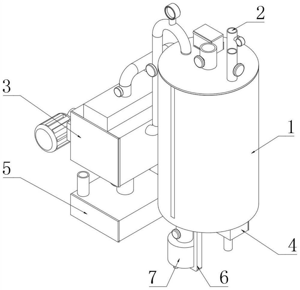
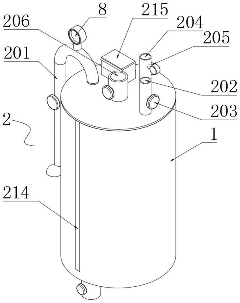
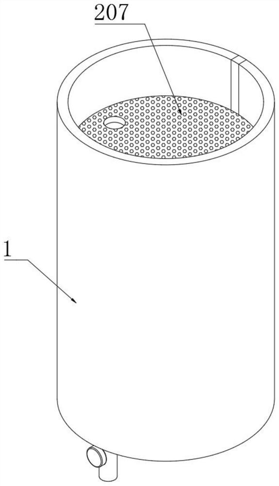
[0057] Example: such as Figure 1-14 As shown, the present invention provides a technical solution for purification and treatment of air pollution, a purification and treatment device for air pollution, comprising a purification tank 1, a purification component 2 is installed on one side of the purification tank 1, and the gas is catalyzed by the purification component 2 , to make it react with each other internally, thereby reducing the amount of chemical reagents used, and at the same time causing some substances to precipitate, effectively saving resources;

[0058] An interception component 3 is installed on one side of the purification tank 1, and the gas is in...


PUM


Abstract

The invention discloses an atmospheric pollution purification and treatment device. A gas inlet pipe penetrates through one side of the top end of a purification tank, an oxygen inlet pipe penetratesthrough one side of the top end of the purification tank, a gas exhaust pipe penetrates through one side of the top end of the purification tank, and a solution inlet pipe penetrates through the middle of the top end of the purification tank; and a transmission motor is connected to the middle of the bottom end of the outer side of the purification tank through a motor base, a bottom end cleaningscraper is welded to the side end of a transmission rod, an electromagnetic heating coil is embedded into the inner side of a clamping cavity, a liquid discharging pipe penetrates through one side ofthe bottom end of the outer side of the purification tank, and a residue discharging pipe penetrates through one side of the bottom end of the outer side of the purification tank. Polluting gas and oxygen are provided for the interior of the tank body through the gas inlet pipe and the oxygen inlet pipe, and meanwhile, a catalyst is added, so that part of gas in the polluting gas and oxygen are subjected to catalytic reaction, meanwhile, the polluting gas reacts with each other, a reaction reagent is provided for the interior after catalysis to accelerate the reaction, and meanwhile, the use of chemical reagents is effectively reduced.

Description

technical field [0001] The invention relates to the technical field of air pollution treatment, in particular to an air pollution purification and treatment device. Background technique [0002] Air pollution is a phenomenon in which certain substances enter the atmosphere due to human activities or natural processes, present in sufficient concentrations for sufficient time, and thus endanger the comfort, health and welfare of the human body or the environment. [0003] However, when the air purification devices currently on the market purify sulfide gas, they directly use a large number of chemical reagents to perform adsorption reactions, which makes the use of reagents large during the purification process, and there is a reaction between some reagents, which affects the purification effect. , At the same time, it is impossible to quickly recycle part of the available resources, resulting in time-consuming and laborious recycling, which greatly affects the efficiency and ...

Claims


Application Information

Patent Timeline
IPC IPC(8): B01D46/10B01D53/86B01D53/88B01D53/52
CPCB01D46/10B01D53/86B01D53/8612B01D53/88B01D2251/102
Inventor 孙雪景
Owner JILIN JIANZHU UNIVERSITY
Learn More