Rotational flow thermal vibration sludge drying machine

A technology of sludge drying and flow heat, which is applied in the direction of dehydration/drying/concentrated sludge treatment, etc., can solve the problems of dangerous components, high moisture content of products, low utilization rate of heat medium, etc., and achieve reuse, transfer High thermal efficiency and high heat exchange efficiency

Inactive Publication Date: 2021-01-29
山东智奇环境技术有限公司
View PDF0 Cites 1 Cited by
  • Summary
  • Abstract
  • Description
  • Claims
  • Application Information

AI Technical Summary

Problems solved by technology

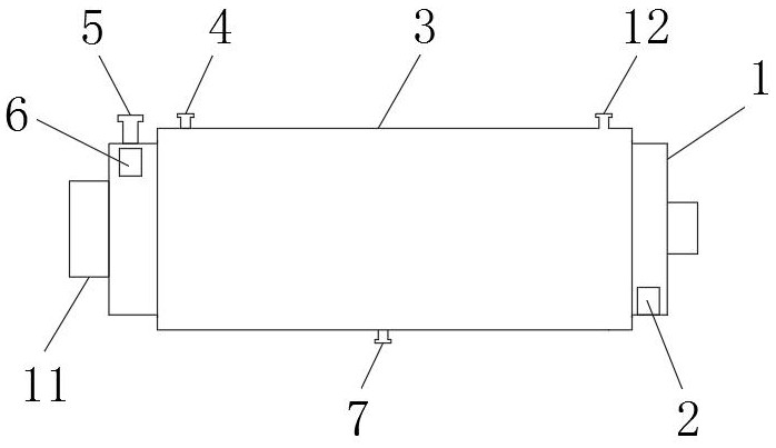
[0004] The purpose of the present invention is to provide a swirl thermal vibration sludge dryer to solve the above-mentioned background technology. In the drying process of the existing equipment, the following shortcomings often occur: 1. The drying effect is poor, and the product contains water 2. The drying equipment is prone to sludge "shaft holding"; 3. The utilization rate of the heat medium is low, and the energy consumption is large and the economy is poor; 4. After the sludge is dried and dehydrated, agglomeration will occur, and the The sludge after the block is easy to block in the drying room, which seriously affects the drying efficiency and service life of the dryer; 5. The sludge has complex components and often contains dangerous components, which is a great test for the safe operation of the dryer The problem

Method used


Image

  • Rotational flow thermal vibration sludge drying machine
  • Rotational flow thermal vibration sludge drying machine
  • Rotational flow thermal vibration sludge drying machine

Examples


Embodiment Construction

[0019] In order to make the technical means, creative features, goals and effects achieved by the present invention easy to understand, the present invention will be further described below in conjunction with specific embodiments.

[0020] In the description of the present invention, it should be noted that the terms "upper", "lower", "inner", "outer", "front end", "rear end", "both ends", "one end", "another end" The orientation or positional relationship indicated by etc. is based on the orientation or positional relationship shown in the drawings, and is only for the convenience of describing the present invention and simplifying the description, rather than indicating or implying that the referred device or element must have a specific orientation, use a specific Azimuth configuration and operation, therefore, should not be construed as limiting the invention. In addition, the terms "first" and "second" are used for descriptive purposes only, and should not be understood ...


PUM


Abstract

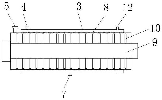
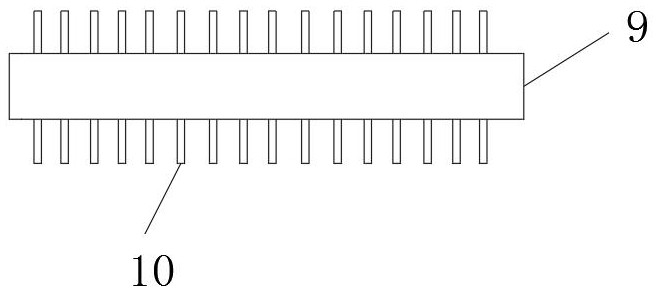
The invention discloses a rotational flow thermal vibration sludge drying machine which comprises a machine body, a rotating shaft is rotatably connected to the interior of the machine body through abearing, blades are detachably connected to the outer side of the rotating shaft through bolts, four blades are evenly distributed on the circumference of each column of the rotating shaft, and the outer side of the machine body is sleeved with a jacket; a spirally-arranged grating is fixedly connected between the jacket and the machine body, a hot oil inlet and a hot oil outlet are formed in theupper end face of the jacket, a hot oil outlet is formed in the lower end face of the jacket, a hot air inlet is formed in the outer side surface of one end of the machine body, and a dry mud outlet is formed in the outer side surface of the other end of the machine body. A wet sludge inlet is formed in the upper end surface of the machine body. The rotational flow thermal vibration sludge dryingmachine is high in heat exchange efficiency, an efficient heat transfer mode combining heat conduction and heat convection is adopted, solid waste sludge with the water content of 80% or above can bedried to the water content of 30% or below, the heat transfer efficiency of rotational flow thermal vibration drying is higher, the drying time is shorter, and the operation cost is lower.

Description

technical field [0001] The invention relates to the technical field of sludge drying, in particular to a swirl thermal vibration sludge drying machine. Background technique [0002] Sludge is a kind of solid waste with complex composition, high moisture content and high viscosity. The drying of sludge is different from conventional substances with single chemical properties. Its drying law and dehydration mechanism are difficult to analyze. The commonly used thermal drying technology is divided into the following Three types: The first is direct drying technology, which adopts the principle of convective heat transfer. Generally, hot air is used as the heat source. The hot air directly contacts the wet mud and transfers heat to the wet mud in the form of heat convection. The water in the wet mud evaporates, and then the drying process is completed. The second is the indirect drying technology. The indirect drying technology adopts the principle of heat conduction and heat tr...

Claims


Application Information

Patent Timeline
Patent Type & Authority Applications(China)
IPC IPC(8): C02F11/13
CPCC02F11/13
Inventor 张振张斌胡成明张肖
Owner 山东智奇环境技术有限公司
Why Eureka
Try Eureka