Supercharge Your Innovation With Domain-Expert AI Agents!

Bias circuit-based low-power-consumption power-on reset circuit and method

A bias circuit, low power consumption technology, applied in electrical components, electronic switches, pulse technology, etc., can solve the problems of high power consumption and high cost, achieve low circuit power consumption, low battery consumption, and simple circuit structure Effect

Active Publication Date: 2021-01-29
广州鸿博微电子技术有限公司
View PDF8 Cites 3 Cited by
  • Summary
  • Abstract
  • Description
  • Claims
  • Application Information

AI Technical Summary

Problems solved by technology

[0005] The embodiment of this application provides a low-power power-on reset circuit and method based on a bias circuit to solve the problem of the MCU power-on reset circuit in the prior art. Open the circuit, the problem of high power consumption and high cost in the circuit

Method used


Image

  • Bias circuit-based low-power-consumption power-on reset circuit and method
  • Bias circuit-based low-power-consumption power-on reset circuit and method
  • Bias circuit-based low-power-consumption power-on reset circuit and method

Examples


Embodiment Construction

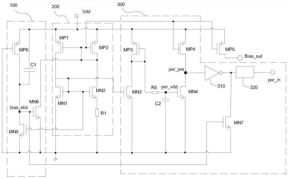
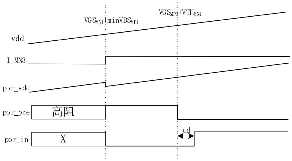
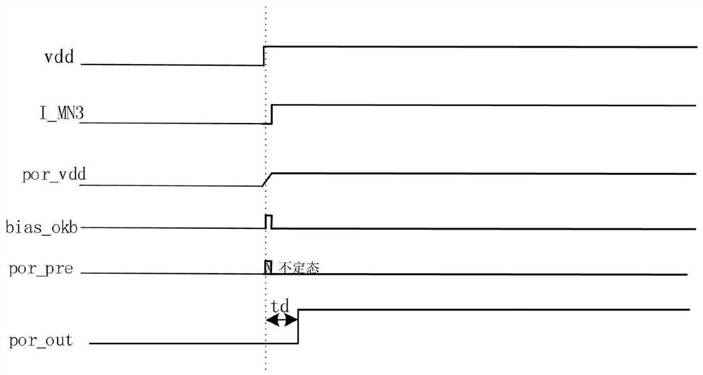
[0034] In order to make the purpose, technical solution and advantages of the present application clearer, specific embodiments of the present application will be further described in detail below in conjunction with the accompanying drawings. It should be understood that the specific embodiments described here are only used to explain the present application, but not to limit the present application. In addition, it should be noted that, for the convenience of description, only parts relevant to the present application are shown in the drawings but not all content. Before discussing the exemplary embodiments in more detail, it should be mentioned that some exemplary embodiments are described as processes or methods depicted as flowcharts. Although the flowcharts describe various operations (or steps) as sequential processing, many of the operations may be performed in parallel, concurrently, or simultaneously. In addition, the order of operations can be rearranged. The proc...


PUM


Abstract

The embodiment of the invention discloses a low-power-consumption power-on reset circuit and method based on a bias circuit. The power-on reset circuit comprises a low-power-consumption bias circuit and a power-on reset circuit, the low-power-consumption biasing circuit is connected with the power-on reset circuit; the low-power-consumption bias circuit comprises a first bias current output end, asecond bias current output end and a high-potential output end; and the power-on reset circuit comprises a third PMOS tube, a fourth PMOS tube, a third NMOS tube, a fourth NMOS tube, a seventh NMOS tube, a Schmitt trigger and a rising edge delayer. The whole circuit structure is simple, the number of elements is small, the number of current branches is small, the current of each branch can be very low, and the elements in the circuit do not work before power-on, so that the circuit power consumption is reduced, the battery consumption is reduced, and the power consumption is reduced. The third NMOS tube, the fourth PMOS tube and the pre-stage multiplexed low-power-consumption bias circuit are used for replacing a large resistor which is usually used for low power consumption and has the resistance value as high as more than ten megabytes, the area of a chip can be remarkably reduced, and the cost of the chip is greatly saved.

Description

technical field [0001] The embodiments of the present application relate to the technical field of reset circuits, and in particular to a low-power power-on reset circuit and method based on a bias circuit. Background technique [0002] MCU is a micro control unit, also known as a single-chip microcomputer or a single-chip microcomputer. Detection circuits such as digital converters, comparators, operational amplifiers, and even LCD drive circuits are integrated on a single chip to form a chip-level computer, which can be used for different combination controls for different applications. [0003] In recent years, with the great development of the Internet of Things and artificial intelligence, the difference between consumer electronics and computers has become smaller and smaller, and the functional requirements of consumer electronics have become higher and higher, and the design has become more and more complex. So many consumer electronics products use MCU as the core ...

Claims


Application Information

Patent Timeline
IPC IPC(8): H03K17/22
CPCH03K17/223
Inventor 郑轩宋振宇黄杨程
Owner 广州鸿博微电子技术有限公司
Features
  • R&D
  • Intellectual Property
  • Life Sciences
  • Materials
  • Tech Scout
  • Unparalleled Data Quality
  • Higher Quality Content
  • 60% Fewer Hallucinations
Learn More