Supercharge Your Innovation With Domain-Expert AI Agents!

Micro magnetic grid for manufacturing magnetic encoder by using magnetron sputtering method, and manufacturing method thereof

A magnetic encoder and magnetron sputtering technology, which is applied in sputtering coating, instruments, and conversion sensor output, etc., can solve the problems of reducing the service life of magnetic encoders, output signal defects, and unfavorable signal processing, etc., and achieve compact structure , solve the effect of low resolution and convenient machining

Pending Publication Date: 2021-02-02
NORTHEAST DIANLI UNIVERSITY
View PDF8 Cites 0 Cited by
  • Summary
  • Abstract
  • Description
  • Claims
  • Application Information

AI Technical Summary

Problems solved by technology

The magnetic gratings for magnetic encoders described in the literature are large in size and low in resolution
At the same time, when the geometric size of the magnetic drum is fixed, when the number of magnetic poles written is increased, the output signal will have defects, which is not conducive to subsequent signal processing, and the manufacturing process in the literature is complicated and difficult to process. If the processing is not accurate, It will reduce the service life of the magnetic encoder

Method used


Image

  • Micro magnetic grid for manufacturing magnetic encoder by using magnetron sputtering method, and manufacturing method thereof

Examples


Embodiment 1

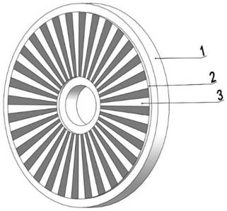
[0052] Such as figure 1Shown, a kind of miniature magnetic grid that makes magnetic encoder with magnetron sputtering method, design profile is disc shape, and the outer diameter of magnetic grid is 60mm, and internal diameter is 12mm, and the center is hole shape, and it comprises: substrate 1, Coating 2, grid 3, the shape of the substrate 1 is disc-shaped, with a round hole in the center, the material of the substrate 1 is monocrystalline silicon, and a coating is set on the ring of the outer surface of the substrate 1. Layer 2, the material of coating 2 is Co-Ni-P-La, and the material of coating 2 Co-Ni-P-La contains: 58.75% (weight percent) Co, 35.25% (weight percent) Ni, 5 % (percentage by weight) P, 1% (percentage by weight) La; a group of grids 3 are set on the coating 2, and the grids 3 are 32 pairs, the size of each magnetic grid is consistent, 360 ° circle The ring is equally divided; the number of magnetic grids determines the number of pulses output per revolution...


PUM


Abstract

The invention relates to a micro magnetic grid for manufacturing a magnetic encoder by using a magnetron sputtering method. The micro magnetic grid comprises a substrate, a coating and grids, the magnetic grid is designed to be in a disc shape and a center hole shape and is convenient to install, the plurality of grids are arranged on the disc and covered with a layer of a magnetic material, the number of the magnetic grids determines the number of pulses output every time the magnetic grids rotate by a circle, and under the same condition, the larger the number of pulses is, the higher the resolution of an encoder is. The invention relates to a manufacturing method of the micro magnetic grid for manufacturing the magnetic encoder by using the magnetron sputtering method. The manufacturingmethod can increase the signal strength, increase the number of grids, improve the resolution ratio of the magnetic encoder, improve the precision and the size in a limited range, can be manufacturedas required, is compatible with a large-scale integrated circuit process, and can be integrally manufactured with an interface circuit.

Description

technical field [0001] The invention relates to the field of magnetron sputtering and the field of magnetic encoder modules, in particular to a micro-magnetic grid for a magnetic encoder manufactured by a magnetron sputtering method and a manufacturing method thereof. Background technique [0002] Rotary encoders are one of the essential components for motion control. The current research on rotary encoders mainly focuses on laser rotary encoders and magnetic rotary encoders. In terms of resolution, the resolution of the magnetic encoder depends on the number of bits of the magnetic drum; under the same conditions, the resolution of the optical encoder is higher than that of the magnetic encoder, because the laser grating can do finer. In the traditional method of making magnetic drums, magnetic drums cannot be made so detailed, so the resolution is lower than that of optical encoders, but optical encoders are not as strong as magnetic encoders in terms of anti-interference...

Claims


Application Information

Patent Timeline
IPC IPC(8): G01D5/245C23C14/35C23C14/54C23C14/16C22C19/07
CPCG01D5/245C23C14/35C23C14/54C23C14/165C22C19/07
Inventor 姜文娟生迪迪
Owner NORTHEAST DIANLI UNIVERSITY
Features
  • R&D
  • Intellectual Property
  • Life Sciences
  • Materials
  • Tech Scout
  • Unparalleled Data Quality
  • Higher Quality Content
  • 60% Fewer Hallucinations
Learn More