
Method for setting GHZ state generation chip based on quantum frequency comb

A frequency comb and quantum technology, applied in the fields of quantum information technology, optical quantum chips and nonlinear optics, can solve the problems of high consumption of space transmission resources, difficulty in preparing high-quality, occupying multiple space channels, etc., to achieve system compatibility, Scalable photon count, easy-to-achieve effects

Active Publication Date: 2021-02-02
NAT UNIV OF DEFENSE TECH
View PDF5 Cites 0 Cited by
  • Summary
  • Abstract
  • Description
  • Claims
  • Application Information

AI Technical Summary

Problems solved by technology

The number of nonlinear parameter conversion units and other experimental devices required by this type of scheme is large, and as the scale expands, the number of required devices and paths also increases. The number of unit devices is generally on the order of O(n), where n is GHZ The total number of photons in the state, such as the scheme in Reference 6, represents the highest level of bulk optical path design, but the optical path is still relatively complex, and with the increase in the number of photons or path modes, it also needs to occupy more time for quantum state transmission. space channel
That is to say, the traditional method of preparing GHZ state has the disadvantages of complex preparation system and large consumption of space transmission resources, and the traditional preparation method of GHZ state adopts bulk optical path, especially the system involves many discrete nonlinear crystals and optical components, which is even more difficult. Difficult to stabilize and prepare high-quality GHZ state

Method used


Image

  • Method for setting GHZ state generation chip based on quantum frequency comb
  • Method for setting GHZ state generation chip based on quantum frequency comb
  • Method for setting GHZ state generation chip based on quantum frequency comb

Examples


Embodiment 1

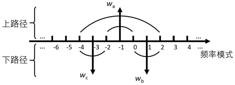
[0040] Example 1: Generation of four-photon polarization-encoded GHZ states. image 3 It is a schematic diagram of the frequency relationship between the pump light and the photon and the corresponding path in the three parameter conversion process when the target state is the four-photon GHZ state. Frequency w of the three pump lasers a 、w b 、w c respectively set at w -1 、w 1 and w -3 on, where the frequency is w a The pump laser of 1 undergoes a parametric conversion process in the upper path, and the other two pump lasers undergo a parametric conversion process in the lower path. The three sets of two-photon frequency combs centered on the frequency of the pump laser are respectively shown in the figure by arcs Indicates that, for example, the arc connecting -2 and 0 represents a photon with a frequency w -2 , another photon at w 0 two-photon state. After the upper and lower paths are combined by a two-dimensional grating, the path information is converted to the p...

Embodiment 2

[0041] Example 2: Generation of six-photon polarization-encoded GHZ states. Figure 4 It is a schematic diagram of the frequency relationship between the pump light and photons and the corresponding paths in the three parameter conversion processes when the target state is a six-photon GHZ state. Frequency w of the three pump lasers a 、w b 、w c respectively set at w -1 、w 1 and w -5 on, where the frequency is w a The pump laser undergoes a parametric conversion process in the upper path, and the other two pump lasers undergo a parametric conversion process in the lower path, resulting in three groups of two-photon frequency combs centered on the pump laser frequency. After the upper and lower paths are combined by a two-dimensional grating, the path information is converted to the polarization direction. At this time, the frequency w -6 、w -4 、w -2 、w 0 、w 2 、w 4 The quantum state in which each frequency mode has one and only one photon is the six-photon GHZ state...

Embodiment 3

[0042] Example 3: Generation of eight-photon polarization-encoded GHZ states. Figure 5 It is a schematic diagram of the frequency relationship between the pump light and photons and the corresponding paths in the three parameter conversion processes when the target state is an eight-photon GHZ state. Frequency w of the three pump lasers a 、w b 、w c respectively set at w -1 、w 1 and w -7 on, where the frequency is w a The pump laser undergoes a parametric conversion process in the upper path, and the other two pump lasers undergo a parametric conversion process in the lower path, resulting in three groups of two-photon frequency combs centered on the pump laser frequency. After the upper and lower paths are combined by a two-dimensional grating, the path information is converted to the polarization direction. At this time, the frequency w -8 、w -6 、w -4 、w -2 、w 0 、w 2 、w 4 、w 6 The quantum state in which each frequency mode has one and only one photon is an eig...


PUM


Abstract

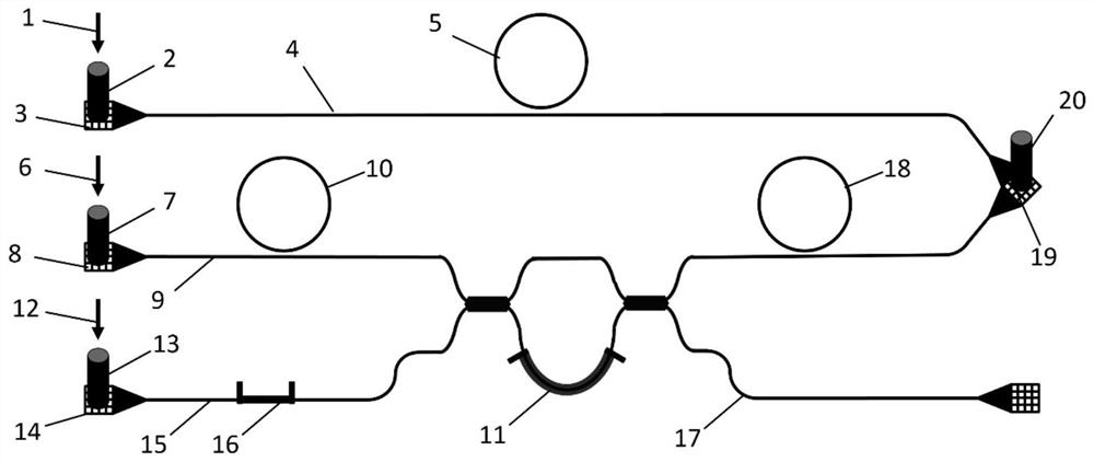
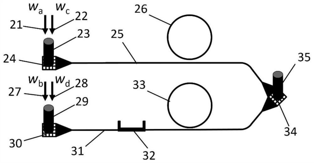
The invention discloses a method for setting a GHZ state generation chip based on a quantum frequency comb. The chip structurally comprises a quantum frequency comb light source and a path polarization converter, the quantum frequency comb light source comprises 2-3 independent and coherent nonlinear optical parameter conversion units capable of generating frequency comb associated photon pairs and a wavelength division multiplexing unit. The quantum frequency comb light source generates two sets of photon pairs covering all frequencies, the photon pairs are output from an upper path and a lower path respectively, two photons output from each path are paired due to energy conservation in frequency, but the upper path and the lower path correspond to two completely different pairing modes to form two items of a GHZ state, and when only one photon exists in each frequency, a frequency-marked multi-photon path coding GHZ state is obtained; and the path polarization converter transfers thepath information of the photons to the polarization degree of freedom to obtain a multi-photon polarization coding GHZ state.

Description

technical field [0001] The invention relates to the fields of quantum information technology, optical quantum chips and nonlinear optics, and is used for preparing scalable frequency-marked multi-photon GHZ states. Background technique [0002] Quantum entanglement is the core resource in quantum information technologies such as quantum communication and quantum computing. The GHZ state, also known as the "Schrödinger's cat" state [1], is the superposition of states in which all subsystem states are different, such as the three-photon GHZ state: The GHZ state has special properties, and its functions include verification of non-locality [2] and quantum error correction [3], etc. The preparation of multiphoton GHZ states has always been a research difficulty and hotspot in the field of quantum information. At present, many experiments on the preparation of multi-photon GHZ states have been reported, including experiments on bulk optical benches[4-6] and optical quantum chi...

Claims


Application Information

Patent Timeline
IPC IPC(8): G02F1/35G02F1/365G02F1/39
CPCG02F1/353G02F1/3501G02F1/365G02F1/39
Inventor 徐平朱枰谕吴俊杰
Owner NAT UNIV OF DEFENSE TECH
Learn More