
Manufacturing method of bidirectional power device

A technology of bidirectional power device and manufacturing method, which is applied in semiconductor/solid-state device manufacturing, electric solid-state device, semiconductor device and other directions, can solve the problems of high power consumption, low device conduction efficiency, etc., to improve performance, reduce bulk resistance, The effect of improving the withstand voltage characteristics

Active Publication Date: 2021-02-02
HANGZHOU SILAN MICROELECTRONICS
View PDF9 Cites 1 Cited by
  • Summary
  • Abstract
  • Description
  • Claims
  • Application Information

AI Technical Summary

Problems solved by technology

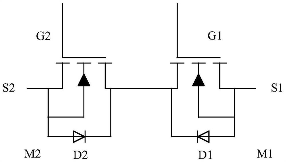
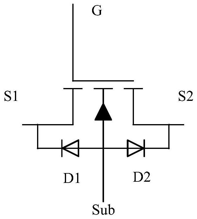
However, the MOS process using a planar gate structure requires sufficient area to meet higher withstand voltage requirements, and at the same time, the conduction efficiency of the device is very low and the power consumption is large

Method used


Image

  • Manufacturing method of bidirectional power device
  • Manufacturing method of bidirectional power device
  • Manufacturing method of bidirectional power device

Examples


Embodiment Construction

[0043] Hereinafter, the present invention will be described in more detail with reference to the accompanying drawings. In the various figures, identical elements are indicated with similar reference numerals. For the sake of clarity, various parts in the drawings have not been drawn to scale. Also, some well-known parts may not be shown. For the sake of simplicity, the semiconductor structure obtained after several steps can be described in one figure.

[0044] It should be understood that when describing the structure of a device, when a layer or a region is referred to as being "on" or "over" another layer or another region, it may mean being directly on another layer or another region, or Other layers or regions are also included between it and another layer or another region. And, if the device is turned over, the layer, one region, will be "below" or "beneath" the other layer, another region.

[0045] If it is intended to describe the situation of being directly on a...


PUM


Abstract

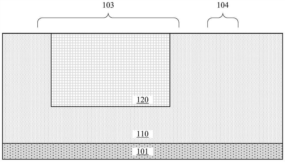
The invention discloses a manufacturing method of a bidirectional power device. The manufacturing method comprises the following steps: forming a first doped region in a semiconductor layer; forming aplurality of trenches in the first trench region, wherein the plurality of trenches of the first trench region are located in the first doped region and divide the first doped region into alternatingfirst-type sub-doped regions and second-type sub-doped regions; forming a gate dielectric layer covering the side walls of the lower parts of the plurality of trenches of the first trench region; forming control gates which are in contact with the gate dielectric layer at the lower parts of the plurality of trenches of the first trench region; forming a shielding dielectric layer, wherein the shielding dielectric layer covers the upper side walls of the plurality of trenches of the first trench region and the surfaces of the control gates; and forming shield gates which are in contact with the shield dielectric layer on the upper portions of the plurality of trenches of the first trench region, wherein the shield dielectric layer separating the control gates from the shield gates. According to the manufacturing method, the first doped region is divided into the first-type sub-doped regions and the second-type sub-doped regions which are alternated by the trenches to form a source region and a drain region of the bidirectional power device, so the area of the device is reduced.

Description

technical field [0001] The present application relates to the technical field of semiconductor manufacturing, and more specifically, to a method for manufacturing a bidirectional power device. Background technique [0002] Bidirectional power devices are widely used in charging devices with a secondary charging function. Taking the lithium battery charging and discharging device as an example, when the lithium battery charging and discharging device continues to supply power to the terminal equipment to a certain extent, it is necessary to prevent the lithium battery from over-discharging to prevent the terminal equipment from stopping, and to charge the lithium battery in time. In the process of charging the lithium battery, the lithium battery also needs to supply power to the terminal equipment, and at the same time prevent the lithium battery from being overcharged. Therefore, in order to manage and control the charge and discharge state of the lithium battery, a charge...

Claims


Application Information

Patent Timeline
IPC IPC(8): H01L21/8232H01L29/06H01L27/02
CPCH01L21/8232H01L21/823878H01L29/0603H01L29/0615H01L29/0684H01L27/0203H01L29/7834H01L29/407H01L29/1041H01L29/1087H01L29/423H01L29/4236H01L29/41766H01L29/66621Y02B70/10
Inventor 杨彦涛张邵华
Owner HANGZHOU SILAN MICROELECTRONICS
Learn More