
Iron wall surface rust removal device

A technology of iron and mounting plate, which is applied in the direction of grinding drive device, grinding/polishing safety device, machine tool suitable for grinding workpiece plane, etc., which can solve the problems of easy rust, influence of workpiece hardness and toughness, and high labor cost and other problems to achieve high efficiency, low rust removal cost, and accelerated rust removal

Pending Publication Date: 2021-02-05
唐华喜
View PDF0 Cites 0 Cited by
  • Summary
  • Abstract
  • Description
  • Claims
  • Application Information

AI Technical Summary

Problems solved by technology

[0002] Iron is a very common material in life, and it is also an irreplaceable material in modern industry. Under normal circumstances, the output of steel can reflect the industrial development level of a country to a certain extent. In the metal activity sequence table, iron ranks In front of hydrogen, the chemical properties are more active, because iron objects are easy to rust, which will have a huge impact on the hardness and toughness of the parts. Small iron objects can be replaced regularly, but once large iron objects are difficult to replace in a short period of time. Replacement, such as iron hulls, iron boilers, etc., requires maintenance, polishing off rust, and coating with anti-rust paint. The usual method is to manually remove rust, compared to iron ground rust removal, because The problem of gravity The derusting of iron walls requires relatively high labor costs

Method used


Image

  • Iron wall surface rust removal device
  • Iron wall surface rust removal device

Examples


Embodiment Construction

[0017] The following will clearly and completely describe the technical solutions in the embodiments of the present invention with reference to the accompanying drawings in the embodiments of the present invention. Obviously, the described embodiments are only some, not all, embodiments of the present invention.

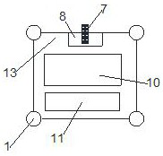
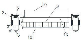
[0018] Combining with the iron wall derusting device shown in 1-2, it includes a mounting plate 13, and the four corners of the mounting plate 13 are provided with a wall running mechanism 1, and the wall running mechanism 1 includes a sleeve 2. The open end of the sleeve 2 is provided with an annular electromagnet 3, and the center of the annular electromagnet 3 runs through a support column 4, and a spring 5 is arranged before the support column 4 and the sleeve 2, and the support column 4 A ball 6 is provided at one end away from the sleeve 2, and a drive mechanism is provided on one side of the mounting plate 13, and the drive mechanism includes a drive motor modu...


PUM


Abstract

The invention discloses an iron wall surface rust removal device which comprises a mounting plate. Wall surface walking mechanisms are arranged at the four corners of the mounting plate correspondingly, each wall surface walking mechanism comprises a sleeve, an annular electromagnet is arranged at the opening end of each sleeve, a supporting column body penetrates through the center of each annular electromagnet, and a spring is arranged between each supporting column body and the corresponding sleeve; balls are arranged at the ends, away from the sleeves, of the supporting columns, a drivingmechanism is arranged at one side of the mounting plate, the driving mechanism comprises a driving motor module and a driving wheel, the driving wheel and the balls make contact with the wall surface,and a plurality of sets of grinding mechanisms are arranged on the mounting plate towards the wall surface; and each grinding mechanism comprises an eccentric wheel vibration module installed on themounting plate, and each eccentric wheel vibration module is connected with a vibration friction plate towards the wall surface. According to the scheme, compared with traditional manual wall rust removal, the cost is lower, the efficiency is higher, and high mechanization and automation are achieved.

Description

technical field [0001] The invention relates to the maintenance technology of industrial equipment products, in particular to an iron wall derusting device. Background technique [0002] Iron is a very common material in life, and it is also an irreplaceable material in modern industry. Under normal circumstances, the output of steel can reflect the industrial development level of a country to a certain extent. In the metal activity sequence table, iron ranks In front of hydrogen, the chemical properties are more active, because iron objects are easy to rust, which will have a huge impact on the hardness and toughness of the parts. Small iron objects can be replaced regularly, but once large iron objects are difficult to replace in a short period of time. Replacement, such as iron hulls, iron boilers, etc., requires maintenance, polishing off rust, and coating with anti-rust paint. The usual method is to manually remove rust, compared to iron ground rust removal, because Th...

Claims


Application Information

Patent Timeline
IPC IPC(8): B24B7/18B24B27/033B24B27/00B24B47/16B24B55/06B24B55/02C23G3/00
CPCB24B7/182B24B27/0007B24B27/033B24B47/16B24B55/02B24B55/06C23G3/00
Inventor 唐华喜
Owner 唐华喜
Learn More