A 3D printed silencer

A muffler device and 3D printing technology, applied in the manufacture of auxiliary devices, instruments, sound-producing instruments, etc., can solve the problems of increased recoil, difficult to clean, and a large number of components, and achieve the effect of reducing the recoil and improving the muffler effect.

Active Publication Date: 2022-07-22
李冉
View PDF24 Cites 0 Cited by
  • Summary
  • Abstract
  • Description
  • Claims
  • Application Information

AI Technical Summary

Problems solved by technology

These devices are mostly designed and processed according to the traditional manufacturing process. Due to the limitation of the subtractive manufacturing process, the number of components is large, the assembly is complicated, the processing steps are many, the sound attenuation effect is general, and the sound attenuation resistance is large, resulting in a large retreat force. Difficult to clean, poor service performance
[0003] The noise reduction characteristics of traditional noise reduction devices are generally single or combined with simple geometric surfaces or bodies such as round holes, cylinders, and cones. The structure is single and the noise reduction effect is average.
Moreover, it must be assembled through several or dozens of single components, each part must be processed, and the tolerances are complex and the manufacturing process is complicated.
Especially used in gun silencers, cleaning and maintenance need to be disassembled, requiring high proficiency of personnel, and poor service performance
In addition, the muffler device composed of simple geometric bodies often cannot solve the two mutually influencing characteristic designs of noise reduction and airflow resistance. When a good noise reduction effect is achieved, the airflow resistance often increases, which brings about the problem of increased recoil. , will affect the accuracy of gun shooting

Method used


Image

  • A 3D printed silencer
  • A 3D printed silencer
  • A 3D printed silencer

Examples


Embodiment

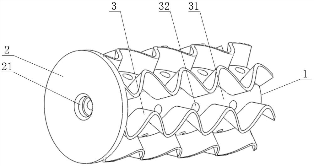
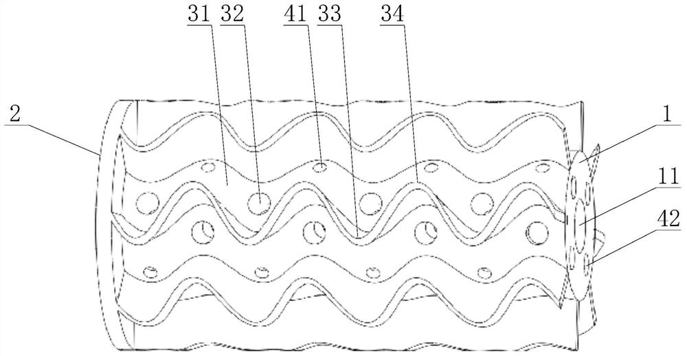
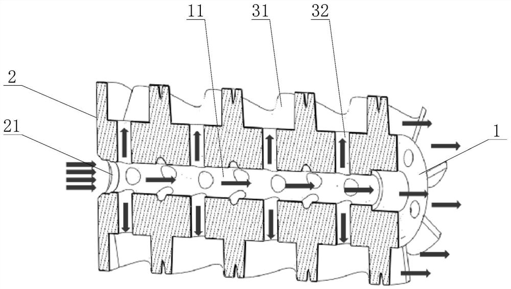
[0024] Example: as attached Figure 1-7 As shown, the present invention is a 3D-printed muffler device, comprising a cylindrical muffler body 1 , a main air passage 11 extending through the muffler body 1 along the axial direction of the muffler body 1 is provided in the middle of the muffler body 1 .

[0025] One end of the muffler body 1 is provided with an air intake end face 2 , and an integrated structure is adopted between the intake end face 2 and the muffler body 1 , and an air inlet 21 communicated with the main air passage 11 is provided in the middle of the air intake end face 2 , the outer diameter of the intake end face 2 is larger than the outer diameter of the muffler body 1 .

[0026] The outer wall of the muffler body 1 is centered on the axis line of the muffler body 1, and the annular array is provided with a plurality of curved expansion chamber airway walls 3, two adjacent curved surface expansion chamber airway walls 3, the air inlet end face 2 and the T...


PUM


Abstract

The invention discloses a 3D-printed muffler device, which mainly relates to the field of mufflers. It includes a cylindrical muffler body, and a main air passage that penetrates the muffler body along the axial direction of the muffler body is provided in the middle of the muffler body; the muffler body One end of the muffler is provided with an air inlet end face; the annular array on the outer wall of the muffler body is provided with several curved expansion chamber air passage walls, and the air passage walls between the two adjacent curved expansion chamber air passage walls, the air inlet end face and the outer wall of the muffler main body are arranged in an annular array. The space is a coupled curved surface expansion chamber air channel, and each of the coupled curved surface expansion chamber air channels and the main air channel is provided with several connecting air channels; the annular array in the muffler body is provided with a number of resonance cavities, each of which is A resonance cavity airway is arranged between the resonant cavity and all the coupled curved surface expansion chamber airways; the present invention can separate the air flow in a small space, realize the shunting and mutual coupling of the inner and outer airways, thereby reducing the noise. At the same time, reducing the pressure increase can effectively control the increase in recoil.

Description

technical field [0001] The invention relates to the field of mufflers, in particular to a 3D printing muffler device. Background technique [0002] The muffler tube or the muffler airway composed of multiple expansion chambers, resonance cavities and other muffler structures is the core device of the muffler. There are two types of typical muffler devices: one is to form a multi-stage expansion chamber through the assembly of multiple muffler bowls to achieve a certain muffler effect; the other is to use a muffler inner tube with multiple holes and a muffler tube to form together The silencing resonance cavity consumes the sound energy through the resonance of the air column to achieve the silencing effect. Most of these devices are designed and processed in accordance with the traditional manufacturing process. Due to the limitation of the subtractive manufacturing process, the number of components is large, the assembly is complex, the processing procedures are many, the ...

Claims


Application Information

Patent Timeline
Patent Type & Authority Patents(China)
IPC IPC(8): B29C64/30B33Y40/00G10K11/16
CPCB29C64/30B33Y40/00G10K11/161
Inventor 李冉
Owner 李冉
Why Eureka
Try Eureka