Method and device for efficiently preparing high-performance coating layer
A high-performance, coating technology, applied in coating, metal material coating process, etc., can solve the problem that the cladding material and the substrate material are very different, the cladding layer is prone to cracking and falling off, and the cladding/substrate interface Solve problems such as large stress, achieve the effect of improving preparation efficiency and performance, improving resistance to fracture and anti-shedding, and improving the matching of thermal expansion coefficient and mechanical properties
- Summary
- Abstract
- Description
- Claims
- Application Information
AI Technical Summary
Problems solved by technology
Method used
Image
Examples
Embodiment 1
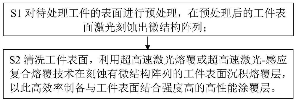
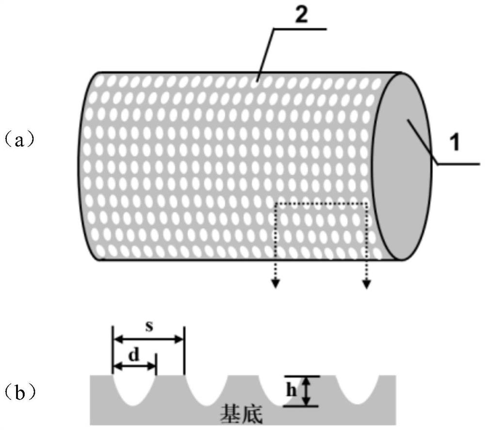
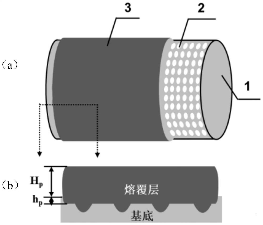
[0063] In this embodiment, laser precision etching is used to process the discrete lattice microstructure array + an ultra-high-speed laser cladding process to prepare a cladding layer on the surface of the shaft workpiece. In this embodiment, a shaft-like workpiece is used as the substrate. First, a discrete pit microstructure array is obtained on the surface of the substrate by using a laser precision etching process, and then a cladding layer is prepared on the roughened microstructure surface by an ultra-high-speed laser cladding process. Specifically, a roll with a roll diameter of 245mm is used as an example for illustration. It is also applicable to solid shaft parts with other roll diameters. The implementation steps include:
[0064] (1) Ni-based alloy powder with a particle size of 25 μm-60 μm is selected as the cladding material, and the main chemical composition is (Wt.%): (0.01-0.50) C, (20-30) Cr, (5-10) W, (3-5)Si, (0-3)B, (5-10)Fe, the balance Ni; the base mate...
Embodiment 2
[0072] In this embodiment, a linear groove microstructure array is processed by laser precision etching + an ultra-high-speed laser-induction composite cladding process is used to prepare a cladding layer on the surface of a shaft workpiece. In this example, the shaft workpiece is used as the substrate. First, the linear groove microstructure array is obtained on the surface of the substrate by laser precision etching processing technology, and then the roughened microstructure surface is prepared by ultra-high-speed laser-induction composite cladding technology. cladding layer. Specifically, a roll with a roll diameter of 100mm is used as an example for illustration. It is also applicable to solid shaft parts with other roll diameters. The specific implementation steps include:
[0073] (1) Co-based alloy powder with a particle size of 25 μm-60 μm is selected as the cladding material, and the main chemical composition is (Wt.%): (0.01-0.5) C, (20-35) Cr, (1-10) Ni, (1-3) Si,...
Embodiment 3
[0081] In this embodiment, a grid-like groove microstructure array is processed by laser precision etching + an ultra-high-speed laser cladding process is used to prepare a cladding layer on the surface of a plate-shaped / block-shaped workpiece. In this embodiment, a block or plate-shaped workpiece is used as the substrate. First, a grid-like groove microstructure array is obtained on the surface of the substrate by using a laser precision etching process. Prepare cladding layer. The specific implementation steps include:
[0082] (1) Ni-based alloy-WC cermet composite powder is selected as the cladding material, wherein the Ni alloy is Ni60 alloy powder with a particle size of 25 μm-60 μm, and the WC is cast WC with a particle size of 20 μm-50 μm. The two are mixed by mechanical mixing; The base material is ordinary low carbon steel;
[0083] (2) Use a fixture to fix the workpiece on the working platform. First, use a grinder or sandpaper to polish the area to be clad on the...
PUM
| Property | Measurement | Unit |
|---|---|---|
| diameter | aaaaa | aaaaa |
| diameter | aaaaa | aaaaa |
| particle diameter | aaaaa | aaaaa |
Abstract
Description
Claims
Application Information
 - R&D
- Intellectual Property
- Life Sciences
- Materials
- Tech Scout
- Unparalleled Data Quality
- Higher Quality Content
- 60% Fewer Hallucinations
Browse by: Latest US Patents, China's latest patents, Technical Efficacy Thesaurus, Application Domain, Technology Topic, Popular Technical Reports.
© 2025 PatSnap. All rights reserved.Legal|Privacy policy|Modern Slavery Act Transparency Statement|Sitemap|About US| Contact US: help@patsnap.com


