Positioning system, positioning method and control method of heavy-load stacking machine

A positioning system and stacker technology, applied in the field of AC motor control, can solve the problems of low positioning accuracy, large debugging workload, delay, etc.

Pending Publication Date: 2021-02-05
江苏智库智能科技有限公司
View PDF0 Cites 2 Cited by
  • Summary
  • Abstract
  • Description
  • Claims
  • Application Information

AI Technical Summary

Problems solved by technology

[0004] However, as far as the heavy-duty stacker is concerned, even if the relatively advanced method of laser ranging is adopted, and the closed-loop speed curve control is used to make the stacker start and stop relatively smoothly, the following problems still generally exist: 1. Due to problems such as stacker shaking and data transmission delay, the positioning accuracy is relatively low; 2. When the positioning equipment fails, it may cause the stacker to lose control and cause an accident; 3. For each cargo location, The position of the stacker needs to be pre-set in the controller, and generally can only be obtained through manual measurement. For large-scale storage projects, the debugging workload is huge

Method used


Image

  • Positioning system, positioning method and control method of heavy-load stacking machine
  • Positioning system, positioning method and control method of heavy-load stacking machine

Examples


Embodiment 1

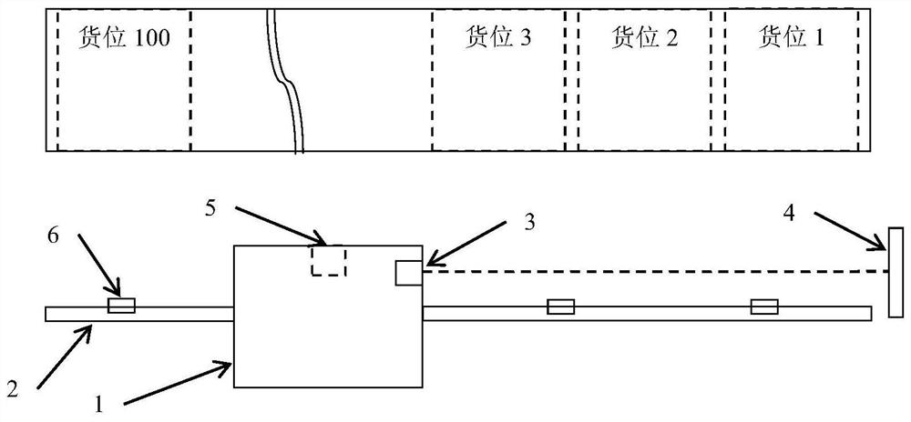
[0077] This embodiment introduces a positioning system for a heavy-duty stacker, refer to figure 1 As shown, the positioning system includes:

[0078] The stacker ground rail is set parallel to the extension direction of multiple stacking stations, and the stacker is slidably installed on the stacker ground rail;

[0079] Reflector, fixed on one side of the stacker rail;

[0080] The laser range finder is installed on the stacker, and the laser emission direction of the laser range finder faces the reflector;

[0081] The reflective sheets are arranged sequentially along the length direction of the stacker's ground rail, and at least one reflective sheet is arranged corresponding to each stacking station;

[0082] The reflective photoelectric sensor is installed on the stacker, and the signal transceiver end of the reflective photoelectric sensor faces the stacker ground rail, and a signal transmission channel is provided between the signal transceiver end and the stacker gr...

Embodiment 2

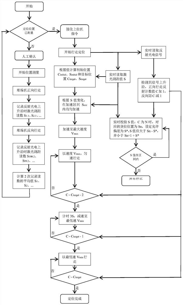
[0088] This embodiment is based on the same inventive concept as Embodiment 1, and introduces the positioning method based on the heavy-duty stacker positioning system in Embodiment 1, including:

[0089] Control the operation of the drive motor of the stacker to drive the stacker to move forward along the ground rail of the stacker;

[0090] In the process of moving forward, in response to receiving the induction signal of the reflective photoelectric sensor, the distance measurement result of the laser range finder is recorded, and the distance measurement result corresponding to each stacking station is taken as the first step of the corresponding stacking station. location data;

[0091] Control the operation of the drive motor of the stacker to drive the stacker to move in reverse along the stacker ground rail;

[0092] In the process of reverse movement, in response to receiving the induction signal of the reflective photoelectric sensor, the distance measurement result...

Embodiment 3

[0102] Based on the same inventive concept as Embodiments 1 and 2, this embodiment introduces a stacker control method, including:

[0103] Obtain the information of the target stacking station and the laser ranging results under the current position of the stacker;

[0104] According to the information of the target stacking station and the current laser ranging results, determine the moving direction of the stacker, the positioning position of the target stacking station, and the positioning position of the current station where the stacker is located;

[0105] According to the preset reflection count reference value corresponding to each stacking station, calculate the positive and negative change direction of the reflection count reference value corresponding to the movement of the stacker from the current position to the target stacking station;

[0106] Control the operation of the driving motor according to the determined moving direction of the stacker to drive the sta...


PUM


Abstract

The invention discloses a positioning system, a positioning method and a control method of a heavy-load stacking machine. The positioning system comprises a stacking machine ground rail, a reflector plate, a laser range finder, a reflector plate, a reflective photoelectric sensor and a controller. The stacking machine ground rail is parallel to the extending direction of a plurality of stacking stations, and the stacking machine is installed on the stacking machine ground rail in a sliding mode. The reflector is fixed on one side of a ground rail of the stacking machine; the laser range finderis installed on the stacking machine, and the laser emitting direction of the laser range finder faces the reflector. The reflector plates are sequentially arranged in the length direction of the stacking machine ground rail corresponding to the stacking stations. The reflection type photoelectric sensor is installed on the stacking machine, wherein the signal receiving and sending end of the reflection type photoelectric sensor faces the stacking machine ground rail. The signal output ends of the laser range finder and the reflective photoelectric sensor are respectively connected with the controller. By means of the system and method, positioning control over the stacking machine with the alternating-current motor without the position feedback function can be achieved, the principle structure is simple, and accuracy and reliability are high.

Description

technical field [0001] The invention relates to the technical field of AC motor control, in particular to a positioning system, a positioning method and a control method of a heavy-duty stacker using an AC motor. Background technique [0002] In the current industry, there are generally two types of motors used in stackers: one uses AC motors and is controlled by frequency converters; the other is using servo motors and is controlled by servo drives. In applications with heavy loads, AC motors are more cost-effective and practical than servo motors. [0003] For heavy-duty stackers using AC motors, since the motor itself does not have encoder position feedback, a positioning device must be added for assistance. At present, there are generally two methods of stacker positioning: absolute addressing and relative addressing, such as barcode positioning, laser positioning, encoder positioning, and reflective sheet positioning. In recent years, laser positioning with high posit...

Claims


Application Information

Patent Timeline
IPC IPC(8): G01S17/08G01S7/48B65G1/04
CPCG01S17/08G01S7/4808B65G1/0407B65G1/0485
Inventor 蔡传玉张家驹
Owner 江苏智库智能科技有限公司
Why Eureka
Try Eureka