
Anti-pollution environment-friendly electroplating wastewater treatment device

A technology for electroplating wastewater and pollution prevention, which is applied in metallurgical wastewater treatment, flotation water/sewage treatment, neutralization water/sewage treatment, etc. A lot of time and other problems, to achieve the effect of easy replacement, safe and convenient use, and accelerated efficiency

Inactive Publication Date: 2021-02-09
孟娜妮
View PDF0 Cites 0 Cited by
  • Summary
  • Abstract
  • Description
  • Claims
  • Application Information

AI Technical Summary

Problems solved by technology

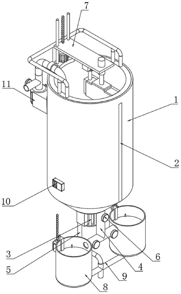
[0004] The present invention provides an environment-friendly electroplating wastewater treatment device that prevents pollution, which can effectively solve the problem that the metal impurities contained in the wastewater will float to the water surface together with the flocs during the aeration treatment of the electroplating wastewater mentioned in the background technology. When the flocs are collected for secondary treatment, it is easy to cause secondary pollution due to metals. At the same time, it is impossible to quickly and effectively separate the flocs, metals and treated wastewater, resulting in a large amount of time required after the treatment is completed. Separation has greatly affected the effect and efficiency of electroplating wastewater treatment

Method used


Image

  • Anti-pollution environment-friendly electroplating wastewater treatment device
  • Anti-pollution environment-friendly electroplating wastewater treatment device
  • Anti-pollution environment-friendly electroplating wastewater treatment device

Examples


Embodiment

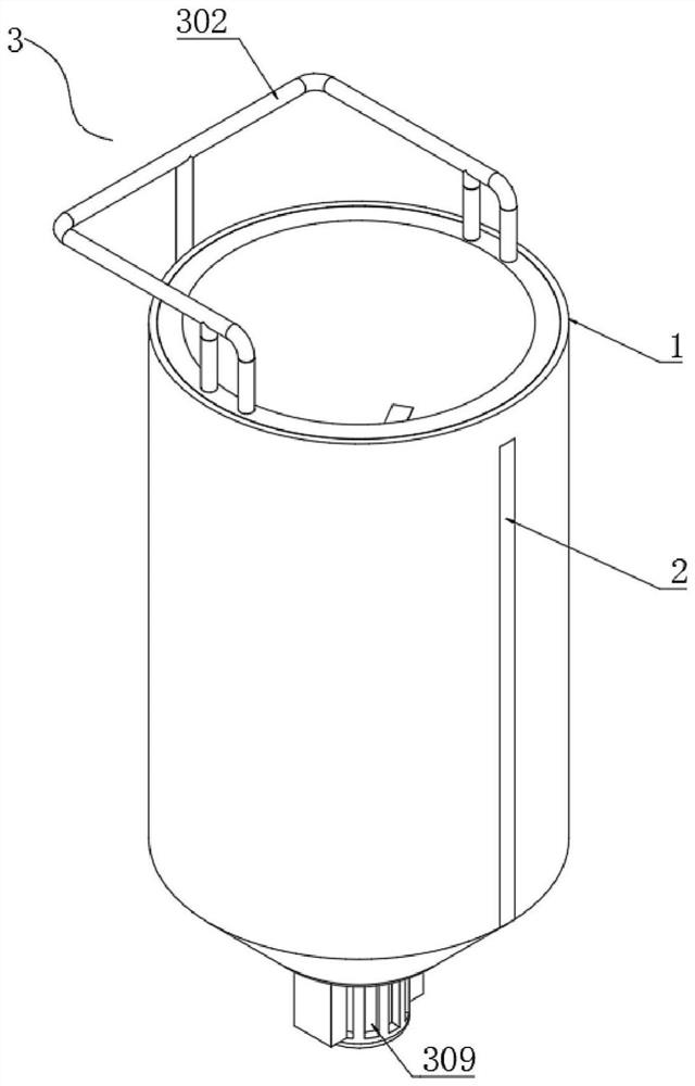
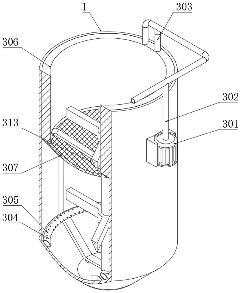
[0054] Example: such as Figure 1-9 As shown, the present invention provides a technical solution for an environmentally friendly electroplating wastewater treatment device that prevents pollution. An environmentally friendly electroplating wastewater treatment device that prevents pollution includes a separation tank 1. One end of the separation tank 1 is embedded with an observation window 2, and an aeration component 3 is installed on the inside of the separation tank 1, and the aeration component 3 is used to aerate it, so that the impurities contained in the wastewater are in the bubbles. Separation and generation of flocs under the action, so as to purify them, and set up interception of flocs, so as to separate metal substances from flocs;

[0055] A collection assembly 7 is installed on the top of the separation tank 1, and the flocs floating on the water surface are collected by the collection assembly 7, which prevents the substance from re-merging into the water aft...


PUM


Abstract

The invention discloses an anti-pollution environment-friendly electroplating wastewater treatment device which is characterized in that an air pump is mounted at one end of the outer side of a separation tank, the air outlet end of the air pump is connected with the air inlet end of an air inlet pipe, one side of the air inlet pipe is connected with an air outlet pipe, and the bottom end of the air outlet pipe is mounted at the top end of an annular air pipe; one end of the air outlet pipe and the side end of the annular air pipe are provided with air outlet holes, a decelerating cylinder isplaced on the inner side of the separation tank, a decelerating net is welded to the bottom end of the decelerating cylinder, a stirring fan is welded to the side end of a transmission rod, an inclined scraping plate is welded to the side end of the transmission rod, the air outlet speed is changed through the air outlet holes, the bubble generation speed is increased, the aeration efficiency is improved, and meanwhile part of metal ions can be subjected to redox reaction, and thus the precipitate of metal compounds is generated, and the speed of flocculate is reduced through the deceleratingcylinder and the decelerating net so that metal impurities can be separated from flocculate and fall to the bottom end of the separation tank, and the wastewater treatment effect and efficiency are guaranteed.

Description

technical field [0001] The invention relates to the technical field of electroplating, in particular to an environment-friendly electroplating wastewater treatment device for preventing pollution. Background technique [0002] The sources of electroplating wastewater are generally plating cleaning water, waste electroplating solution, other wastewater, and equipment cooling water. The water quality and quantity of electroplating wastewater are related to factors such as the process conditions of electroplating production, production load, operation management, and water use methods. Contains chromium, cadmium, nickel, copper, zinc, gold, silver and other heavy metal ions and cyanide, some of which are highly toxic substances that are carcinogenic, teratogenic, and mutagenic. [0003] However, when the electroplating wastewater currently on the market is aerated, the metal impurities contained in the wastewater will float to the water surface together with the flocs. When the...

Claims


Application Information

Patent Timeline
IPC IPC(8): C02F9/04C02F103/16
CPCC02F1/001C02F1/24C02F1/38C02F1/66C02F9/00C02F2103/16
Inventor 孟娜妮
Owner 孟娜妮
Learn More