
Low-pressure steam source boosting heat supply method for combined heat and power generation unit

A cogeneration unit and low-pressure steam technology, which is applied in steam central heating systems, heating methods, household heating, etc., can solve the problems of large heating flow, low power of generator sets, and reduction, so as to improve flexibility, The effect of enhancing the steam supply capacity

Active Publication Date: 2021-02-09
ELECTRIC POWER RES INST OF GUANGXI POWER GRID CO LTD
View PDF9 Cites 4 Cited by
  • Summary
  • Abstract
  • Description
  • Claims
  • Application Information

AI Technical Summary

Problems solved by technology

The steam flow rate of the steam turbine is directly related to the output of the generator. If the steam flow rate of the steam turbine is large, the output power of the generator will be large, and if the steam flow rate of the steam turbine is small, the output power of the generator will be small; The power of the unit is large; the heat supply flow is small, and the power of the generator set is required to be small; under the heating condition of the cogeneration unit, the electric power of the generator unit cannot be flexibly adjusted to meet the requirements of peak regulation and valley filling of the power grid; the pure condensing steam turbine is used for large-area thermal power generation. After the co-generation transformation, the peak-shaving unit and capacity will be greatly reduced. The large-scale promotion of clean energy such as large-capacity nuclear power units with base loads and intermittent wind and photovoltaic power generation forms will significantly increase the impact on the power grid. To the safe and stable operation of the power grid

Method used


Image

  • Low-pressure steam source boosting heat supply method for combined heat and power generation unit
  • Low-pressure steam source boosting heat supply method for combined heat and power generation unit

Examples


Embodiment Construction

[0036] The following will clearly and completely describe the technical solutions in the embodiments of the present invention with reference to the accompanying drawings in the embodiments of the present invention. Obviously, the described embodiments are only some, not all, embodiments of the present invention. Based on the embodiments of the present invention, all other embodiments obtained by persons of ordinary skill in the art without creative efforts fall within the protection scope of the present invention.

[0037] It should be noted that when an element is considered to be "connected" to another element, it may be directly connected to the other element or there may be an intervening element at the same time. When an element is said to be "disposed on" another element, it can be directly disposed on the other element or intervening elements may also be present.

[0038] Unless otherwise defined, all technical and scientific terms used herein have the same meaning as com...


PUM


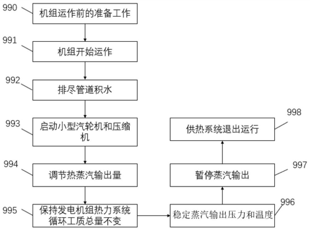
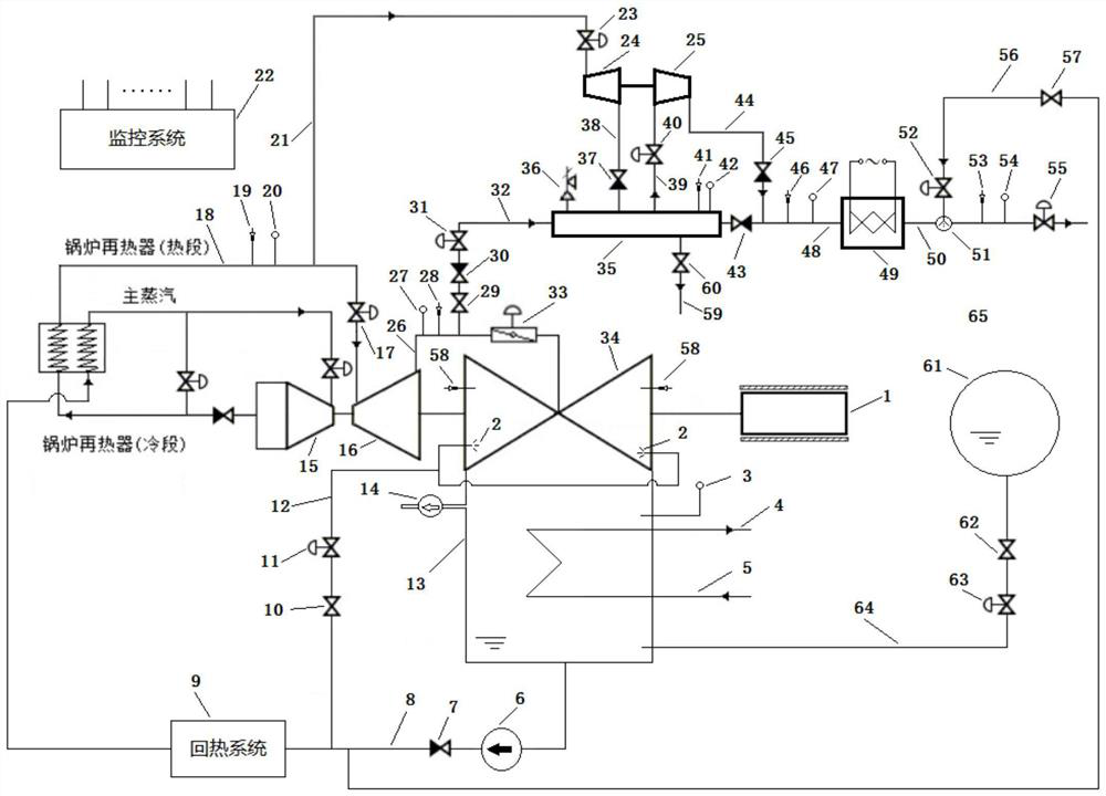
Abstract

The invention discloses a low-pressure steam source boosting heat supply method for a combined heat and power generation unit. The low-pressure steam source boosting heat supply method for the combined heat and power generation unit comprises the following steps that S101, preparation work before unit operation is conducted; S102, the unit starts to operate; S103, accumulated water in a pipeline is drained as much as possible; S104, a small steam turbine and a compressor are started; S105, the output quantity of hot steam is adjusted; S106, the total amount of cycle working fluid of a thermalpower system of a generator set is kept unchanged; S107, the steam output pressure and temperature are stabilized; S108, the steam output is paused; and S109, a heat supply system quits operation. Themethod can effectively solve the problem that heat supply steam pressure and temperature are flexibly adjusted under the condition that parameters such as through-flow steam pressure and temperatureof a turbine bleed point cannot meet user requirements, so that the heat supply steam parameters meet the requirements of heat consumers, the method does not excessively depend on the method of increasing the electric power of the generator set to increase the steam flow of the steam turbine in order to enhance the steam supply capacity of the unit, and the flexibility of greatly adjusting the electric power of the generator is also improved.

Description

technical field [0001] The invention relates to the technical field of heat supply and power generation and its control analysis, in particular to a method for boosting heat supply from a low-pressure steam source of a heat and power cogeneration unit. Background technique [0002] At present, it is proposed to optimize the industrial and energy structure, reduce the consumption of scattered coal and fuel oil; strengthen the reduction of major pollutants, accelerate the development of cogeneration and centralized heating, and use the existing cogeneration units and pure condensing power generation around cities and industrial parks. A series of requirements such as the implementation of heat supply transformation for units and low-grade waste heat, and the elimination of coal-fired boilers (kilns) within the scope of heat supply and gas supply. [0003] In response to the requirements of the national energy conservation and environmental protection policy, small industrial b...

Claims


Application Information

Patent Timeline
Patent Type & Authority Applications(China)
IPC IPC(8): F24D1/06F24D1/08F24D19/10F22G1/16F22G5/12F01D15/10F01K11/02F01K13/00F01K13/02F01K17/02
CPCF24D1/06F24D1/08F24D19/1003F22G1/165F22G5/123F01D15/10F01K11/02F01K13/003F01K13/02F01K17/025Y02E20/16
Inventor 文立斌
Owner ELECTRIC POWER RES INST OF GUANGXI POWER GRID CO LTD
Learn More