Manufacturing method of cam component and its application in textile machinery

A production method and component technology, which are applied in the production of precision cam components in textile machinery and in the field of production of cam components, can solve the problems of high cost, high resistance to sintering and compactness, time-consuming and high cost, and achieve fast and fast manufacturing with less Adhesion, effect of high mechanical properties

Active Publication Date: 2021-09-28
SANYANG TEXTILE
View PDF15 Cites 0 Cited by
  • Summary
  • Abstract
  • Description
  • Claims
  • Application Information

AI Technical Summary

Problems solved by technology

[0002] Many cam parts in precision mechanical equipment have small size and complex shape, such as presser cams in textile machinery and similar structures. Conventional machining methods are difficult and inefficient, so companies sometimes use MIM (metal Injection molding) process to manufacture, in the specific MIM process operation, because the metal powder needs to have good rheological ability to be injection molded, so the particle size of the metal powder needs to be very small, and the amount of the rheological binder is also Larger, the smaller the particle size of the metal powder, the more expensive the cost, the greater the amount of binder used, the higher the time and cost of the degreasing process, the greater the resistance to sintering densification, and the risk of inherent defects in the product also increases, and, For some products with fine and complex shapes, the MIM process often does not meet the dimensional accuracy requirements due to the large deformation of the product after degreasing and sintering. In addition, because the MIM process is a one-time injection and integral forming, it is generally not possible to adjust different parts of the same part according to needs. Partition design made of metal materials
[0003] In terms of powder cost, binder consumption, product sintering deformation, material design, etc. mentioned above, the MIM process is not as good as the traditional powder metallurgy process (pressing + sintering, hot pressing), but the traditional powder metallurgy process Since the powder needs to be pressed by pressure in a specific direction (such as axial force), the conduction of pressure is not as random as that of rheological pressure. Therefore, the shape of the product and the structure of the mold must be as simple as possible, and a slightly more complex product cannot be implemented.

Method used


Image

  • Manufacturing method of cam component and its application in textile machinery
  • Manufacturing method of cam component and its application in textile machinery
  • Manufacturing method of cam component and its application in textile machinery

Examples


Embodiment 1

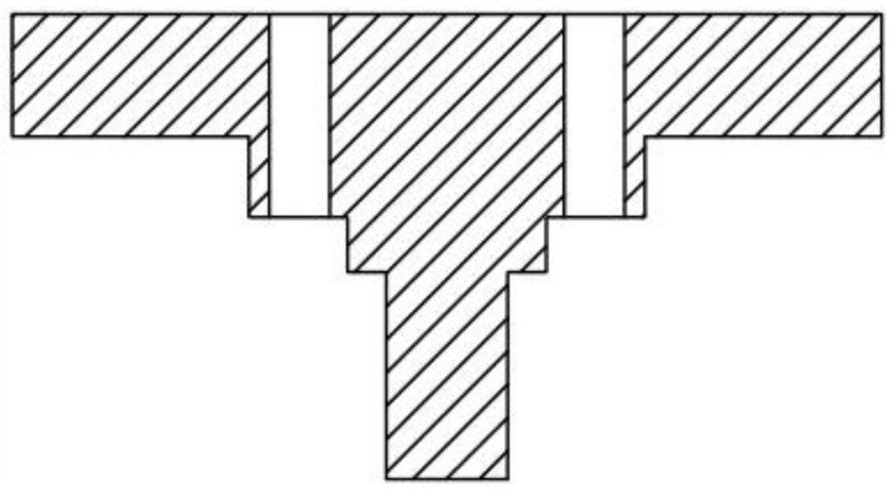
[0032] see Figure 1-Figure 5 , a method for manufacturing a cam component in this embodiment at least includes the following steps:

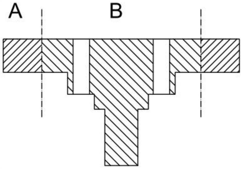
[0033] 1. Disassemble the overall part model of the cam component, and split the overall part model of the cam component into a wheel edge part A with a relatively simple shape and a shaft core part B with a relatively complex shape;

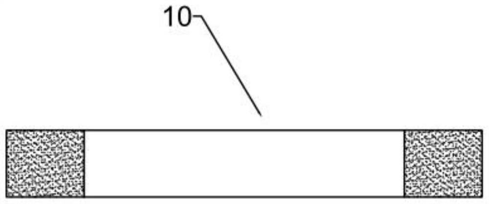
[0034] 2. The above-mentioned wheel edge part A of the cam part is produced by the molding and sintering process in the powder metallurgy process, specifically: select the wheel edge part metal powder according to the wheel edge part material, directly put the wheel edge part metal powder into the pressing mold, or put The metal powder at the wheel edge is mixed with a binder with a mass content not higher than 6%, and then loaded into a pressing mold, and pressure is applied to the pressing mold to compact the metal powder at the wheel edge into a powder compact, and the powder compact is demoulded Then put it ...

Embodiment 2

[0041] This embodiment is a further improvement on Embodiment 1. In this embodiment, in step 3, the rim portion cavity 31 is configured to be able to squeeze the sintered rim portion finished product 10 so that the sintered The material of the finished wheel edge part 10 produces a certain degree of flow and compression. The advantage of this solution is that it can reduce the requirements for molds and equipment when the sintered wheel edge part product 10 is prepared by the molding and sintering process, and the pressing pressure can be appropriately reduced. , and can be sintered in batches in the sintering furnace without hot pressing. When the sintered wheel edge product 10 is not enough to meet the compactness requirement by using the molding sintering process, the sintered wheel edge product 10 is implemented through the wheel edge cavity 31. Extrusion causes the material of the finished sintered wheel edge part 10 to flow and compress to a certain extent to achieve the ...


PUM

PropertyMeasurementUnit
particle diameteraaaaaaaaaa

Abstract

The manufacturing method of the cam component is to split the whole part model of the cam component into a relatively simple wheel edge part and a relatively complex shaft core part through the part design method of changing the whole into parts, and adopts the molding method in the powder metallurgy process The rim part of the cam part is produced by sintering process, the shaft core part of the cam part is produced by MIM process, and the sintered wheel is placed in the cavity of the "assembly-shaping" integrated tool under the condition of heating at least the finished sintered wheel part The finished edge part is hot-press assembled to the outer ring of the finished sintered shaft core part, and at the same time, the shaping of the whole part of the cam part is completed in the cavity. This method enables the complex shape of the shaft core to be well realized in injection molding, while the wheel edge can be quickly manufactured in a low-cost, less-adhesive, high-pressure and high-density manner. Shaping, assembly, and extrusion are completed in one step. Manufacturing The size, shape and mechanical properties of the products meet the requirements. This method is especially suitable for the manufacture of cam parts in textile machinery.

Description

technical field [0001] The invention relates to the technical field of manufacturing mechanical transmission components, in particular to a method for manufacturing a cam component, and is particularly applicable to the manufacture of precision cam components in textile machinery. Background technique [0002] Many cam parts in precision mechanical equipment have small size and complex shape, such as presser cams in textile machinery and similar structures. Conventional machining methods are difficult and inefficient, so companies sometimes use MIM (metal Injection molding) process to manufacture, in the specific MIM process operation, because the metal powder needs to have good rheological ability to be injection molded, so the particle size of the metal powder needs to be very small, and the amount of the rheological binder is also Larger, the smaller the particle size of the metal powder, the more expensive the cost, the greater the amount of binder used, the higher the t...

Claims


Application Information

Patent Timeline
Patent Type & Authority Patents(China)
IPC IPC(8): B22F5/08B22F3/02B22F3/22
CPCB22F5/08B22F3/225B22F3/02
Inventor 张尧宗郭永林
Owner SANYANG TEXTILE
Why Eureka
Try Eureka