Automatic-control humidification energy-saving fresh air system

A technology of fresh air system and humidification device, applied in the field of air purification, can solve problems such as affecting comfort

Inactive Publication Date: 2021-02-12
广州新小丹利贸易有限公司
View PDF0 Cites 2 Cited by
  • Summary
  • Abstract
  • Description
  • Claims
  • Application Information

AI Technical Summary

Problems solved by technology

[0003] The fresh air discharged by the current fresh air system is relatively dry, which affects the comfort of use and causes many people to suffer from respiratory diseases. Therefore, we propose a self-controlled humidification and energy-saving fresh air system

Method used


Image

  • Automatic-control humidification energy-saving fresh air system
  • Automatic-control humidification energy-saving fresh air system
  • Automatic-control humidification energy-saving fresh air system

Examples


Embodiment 1

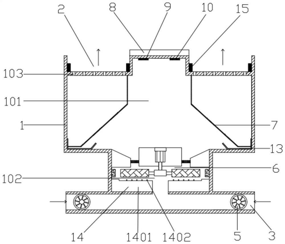
[0058] An embodiment of the present invention provides a self-controlled humidification and energy-saving fresh air system, such as Figure 1-5 As shown, it includes a housing 1, an air inlet 3 and an air outlet 2;

[0059] The housing 1 is provided with a first cavity 101, a second cavity 102 and a plurality of through holes 103, and the plurality of through holes 103, the first cavity 101 and the second cavity 102 are sequentially connected up and down, so that The plurality of through holes 103 are uniformly arranged on the upper part of the housing 1;

[0060] The air outlet 2 is arranged on the top of the housing 1, and the air outlet 2 communicates with the through hole 103 up and down; the number of the air inlet 3 is two, and the air inlet 3 is symmetrically arranged at the bottom of the housing 1;

[0061] The self-controlled humidification and energy-saving fresh air system also includes:

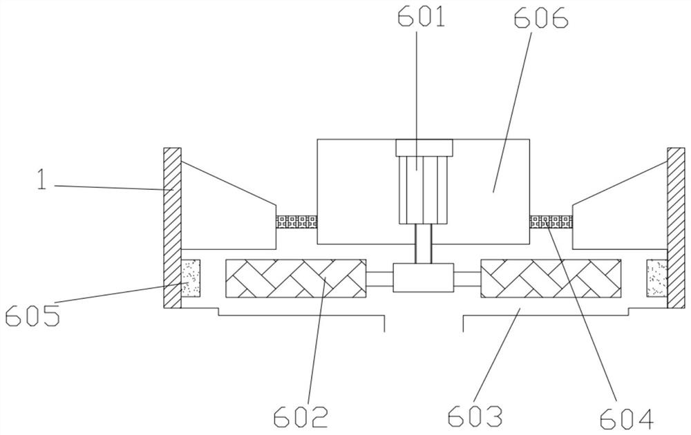
[0062] An automatic humidifying device 14, the automatic humidifying device...

Embodiment 2

[0071] On the basis of above-mentioned embodiment 1, as figure 1 As shown, the housing 1 is provided with a temperature sensor 9 and a humidity sensor 10 at the air outlet 2, which are respectively used to detect the temperature and humidity at the air outlet 2, and the housing 1 is also provided with a controller. The controller is electrically connected with the power supply, the temperature sensor one 9 , the humidity sensor 10 and the automatic humidifying device 14 .

[0072] The beneficial effect of the above technical solution is: turn on the power, after the air enters the first cavity 101, the humidity sensor installed inside the first cavity 101 detects the humidity of the air, and after the air enters the air outlet 2, it is set in the through hole The temperature sensor-9 on the outer end surface of -103 detects the temperature of the outflowing air, and can monitor the air humidity and temperature inside the casing 1 .

Embodiment 3

[0074] On the basis of Example 1, such as figure 1 As shown, the number of the air outlets 2 is two, the two air outlets 2 are symmetrically arranged on the top of the housing 1, and the top of the housing 1 is fixed with a display screen 8 between the air outlets 2, The left and right sides of the inner wall of the air outlet 2 are symmetrically provided with heaters 15, and the display screen 8 and the heater 15 are respectively electrically connected to the controller.

[0075] The beneficial effect of above-mentioned technical scheme is:

[0076] The user can adjust the temperature of the air flowing out of the air outlet 2 by adjusting the heater 15, so as to be suitable for different temperature environments, and the display screen 8 electrically connected with the temperature sensor one 9 and the humidity sensor 10 shows the temperature value and humidity of the air value, which serves as a reminder to the user, so that the user can know the air temperature and humidit...


PUM


Abstract

The invention provides an automatic-control humidification energy-saving fresh air system which comprises a shell, and a first cavity, a second cavity and a plurality of through holes are formed in the shell; the multiple through holes are evenly distributed in the upper end face of the shell, and the multiple through holes, the first cavity and the second cavity sequentially communicate in the vertical direction; two air outlets are formed in the top of the shell in a bilateral symmetry mode, and the air outlets vertically communicate with the through holes; two air inlets are symmetrically formed in the bottom of the shell; an automatic humidifying device is arranged in the second cavity of the shell; and two filter membranes are symmetrically and obliquely arranged in the first cavity of the shell. According to the automatic-control humidification energy-saving fresh air system, due to the fact that a pollutant removal assembly is adopted, the pollutant removal capacity is greatly improved, the air inlets communicate with the pollutant removal device, the purposes of removing pollutants and purifying air can be achieved, and therefore, the problem that an existing humidificationenergy-saving fresh air system cannot filter out pollutants in air can be solved.

Description

technical field [0001] The invention relates to the technical field of air purification, in particular to a self-controlled humidification and energy-saving fresh air system. Background technique [0002] With the development of industrialization and the continuous increase of population in our country, the pollution is also becoming more and more serious. In buildings, pollutants produced due to more and more gorgeous decorations and other factors have a serious impact on indoor air quality. These pollutants have serious damage to the human respiratory system, cardiovascular system and nervous system. In the car, due to the infiltration of exhaust gas from the engine and the emission of interior decoration materials, pollutants such as formaldehyde, acetaldehyde, acetic acid, benzene, ammonia, nitrogen oxides, acetone, xylene, etc., sometimes reach quite high levels. concentration. Therefore, it is an urgent problem to design and develop a device for eliminating pollutant...

Claims


Application Information

Patent Timeline
Patent Type & Authority Applications(China)
IPC IPC(8): F24F7/003F24F7/007F24F6/18F24F8/108F24F11/30F24F11/52F24F13/28B60H1/00B60H3/02F24F110/10F24F110/30
CPCB60H1/00785B60H1/00792B60H3/022B60H2003/026F24F6/18F24F7/007F24F11/0008F24F13/28F24F11/30F24F11/52F24F2110/10F24F2110/30Y02T10/88
Inventor 刘朝丽
Owner 广州新小丹利贸易有限公司
Why Eureka
Try Eureka