
External electric meter box

A technology of electric meter box and box, which is applied in measuring devices, measuring electric variables, dispersing particle filtration, etc., can solve the problems of shortening the service life of electric meters and other power accessories, water vapor entering, etc., so as to reduce the possibility and safety risks. Effect

Active Publication Date: 2021-02-12
BEIJIG YUPONT ELECTRIC POWER TECH
View PDF9 Cites 2 Cited by
  • Summary
  • Abstract
  • Description
  • Claims
  • Application Information

AI Technical Summary

Problems solved by technology

[0005] Based on the existing technical problem that water vapor enters the meter box due to the arrangement of multiple heat dissipation holes, resulting in shortened service life of the meter and other power accessories, the present invention proposes an external meter box

Method used


Image

  • External electric meter box
  • External electric meter box
  • External electric meter box

Examples


Embodiment 1

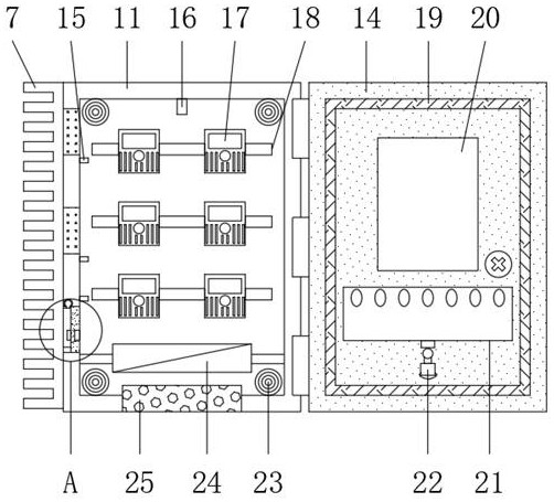
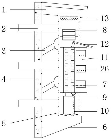
[0037] refer to Figure 1-8, an external electric meter box, including an M-shaped frame 4, a plurality of positioning columns 2 are plugged at both ends of the M-shaped frame 4, and two groups of multiple positioning columns 2 are fixedly installed with a lifting frame 5 at one end, and inside the lifting frame 5 A box body 11 is provided, tooth plates 7 are fixedly installed on both sides of the box body 11, a drying cylinder 23 is fixedly installed on both sides of the top and bottom inner walls of the box body 11, and a filter mechanism 25 is mounted on the bottom end of the box body 11. The lower end of the inner wall of 11 is fixedly installed with an exhaust fan 24 through a bracket, a temperature and humidity sensor 16 is fixedly installed in the middle of the inner wall at the top of the box body 11, a plurality of smoke sensors 15 are fixedly installed on the inner walls on both sides of the box body 11, and multiple smoke sensors 15 are fixedly installed on the inner...

Embodiment 2

[0052] refer to Figure 9 , an external electric meter box, further, a U-shaped rod 38 is fixedly installed on one side of the inner wall of the box door 14, and a third hydraulic column 37 is fixedly installed on the other side of the inner wall of the box door 14, and the bottom end of the third hydraulic column 37 is fixed A cotton brush 39 is installed, and one end of the cotton brush 39 is socketed with the U-shaped rod 38 .

[0053] Working principle: through the third hydraulic column 37 stretching and contracting regularly, the cotton brush 39 is driven to move up and down on the surface of the U-shaped rod 38, and the water vapor and liquid droplets on the inner wall of the observation window 20 are absorbed and cleaned.


PUM


Abstract

The invention belongs to the technical field of electric power accessories, particularly relates to an external electric meter box, and aims to solve the problem that the service life of an electric meter and other electric power accessories is shortened due to the fact that water vapor enters the electric meter box due to the fact that a plurality of heat dissipation holes are formed in the electric meter box in the prior art. According to the scheme, the electric meter box comprises an M-shaped frame, and a plurality of positioning columns are inserted into the two ends of the M-shaped frame; and lifting frames are fixedly mounted at one ends of the two sets of positioning columns correspondingly, box bodies are arranged in the lifting frames, and toothed plates are fixedly mounted on the outer walls of the two sides of each box body. Real-time detection is conducted through a temperature and humidity sensor, the number of opened movable plates and the rotating angles of the movableplates are determined according to the set temperature gradient limit value, an electromagnet is powered on to enable the movable plates to pop up and an elastic curtain to be pulled open, an exhaustfan works, and convection and heat exchange are conducted on external cold air and internal hot air; and the electromagnet is powered off to reset the movable plate to be clamped with the silica gel clamping seat, so that the possibility that external water vapor enters the box body in cloudy and rainy days is greatly reduced.

Description

technical field [0001] The invention relates to the technical field of electric power accessories, in particular to an external electric meter box. Background technique [0002] As a commonly used power distribution device in power distribution lines or metering lines, the meter box is an indispensable equipment in the transmission network. There are multiple meters safely placed inside the meter box to record the power consumption. The material of the box is a Resin-based composite materials are composed of matrix-polyester resin and reinforcing materials. During production, they are mainly made of ABS engineering plastics, polycarbonate transparent PC materials, DMC and SMC by injection molding and pressing. [0003] The meter box has the following characteristics: completely solve personal injury accidents caused by poor grounding and foreign matter lapping, low comprehensive use cost and long life, effectively resist external impact, high cost of box material recycling t...

Claims


Application Information

Patent Timeline
Patent Type & Authority Applications(China)
IPC IPC(8): G01R11/04B01D46/12B01D46/00B01D53/02B01D53/26
CPCG01R11/04B01D46/12B01D53/02B01D53/266B01D53/261B01D2257/80B01D46/56
Inventor 张悦王巧年
Owner BEIJIG YUPONT ELECTRIC POWER TECH
Learn More