Electrode wire

A technology of electrode wires and connecting wires, applied in the direction of electrodes, internal electrodes, epicardial electrodes, etc., can solve the problems of unsatisfactory implantation effect and difficult implantation head, and achieve simple structure, convenient implantation and smooth operation Effect

Pending Publication Date: 2021-02-19
MEI HOSPITAL UNIV OF CHINESE ACAD OF SCI
View PDF0 Cites 0 Cited by
  • Summary
  • Abstract
  • Description
  • Claims
  • Application Information

AI Technical Summary

Problems solved by technology

[0003] One end of the existing electrode wire implanted in the body tissue is made into a helical shape, so that the implanted end can break through the endocardium and reach the pacing site through the helical screwing method; however, due to the closer the bundle of His in the ventricle The closer the area is to the physiological pacing site, but the closer to the His bundle, the more developed the fibrous scaffolding system, the conventional helical implant head is difficult to break through, and the implantation effect is not ideal

Method used


Image

  • Electrode wire
  • Electrode wire
  • Electrode wire

Examples


Embodiment 1

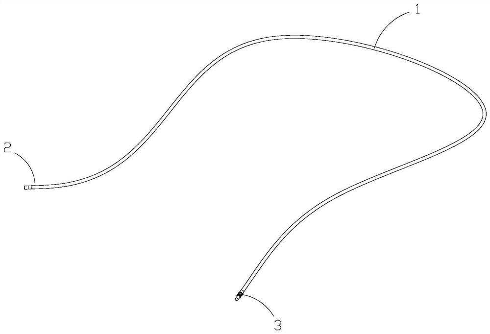
[0047] Such as Figure 1-17 As shown, an electrode lead includes a connection wire 1, an implant end 2 and a connection end 3; the implant end 2 is used to connect with the patient's myocardial tissue, the connection end is used to connect with a cardiac pacemaker, and the connection wire is Used to connect the implant end and the connection end.

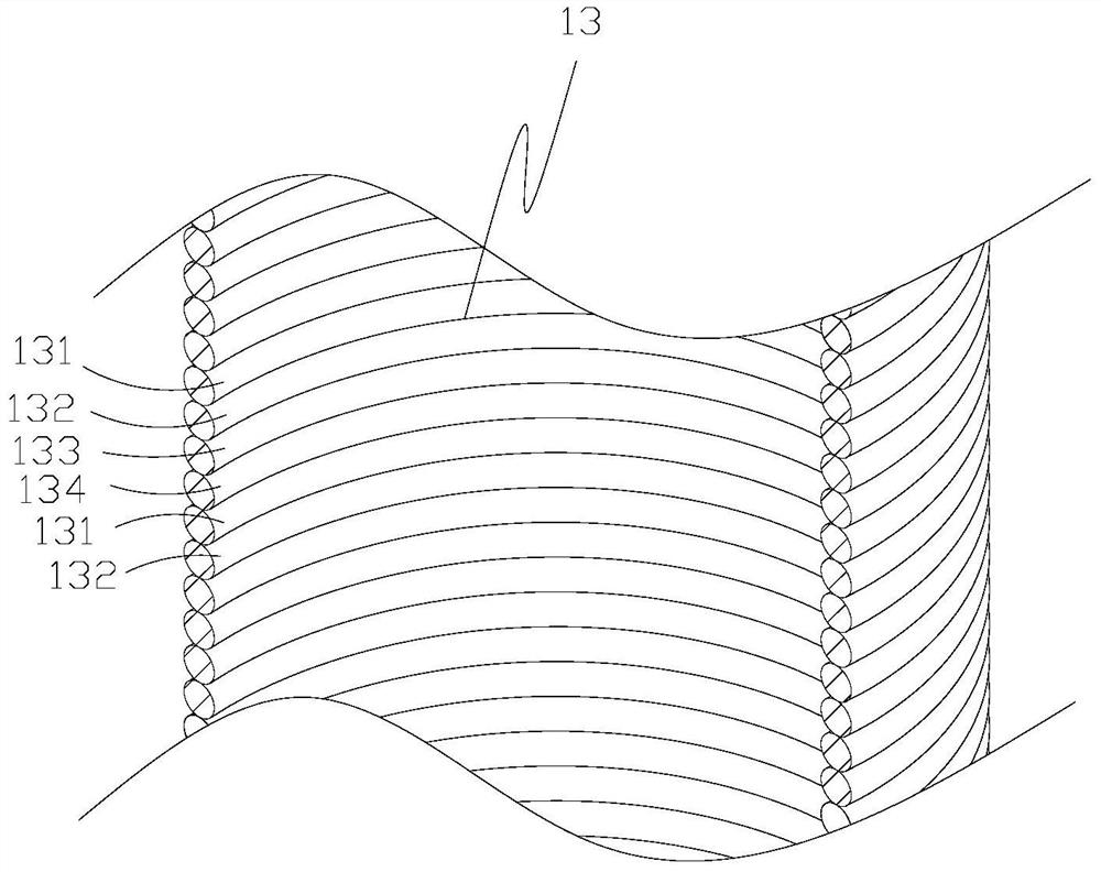
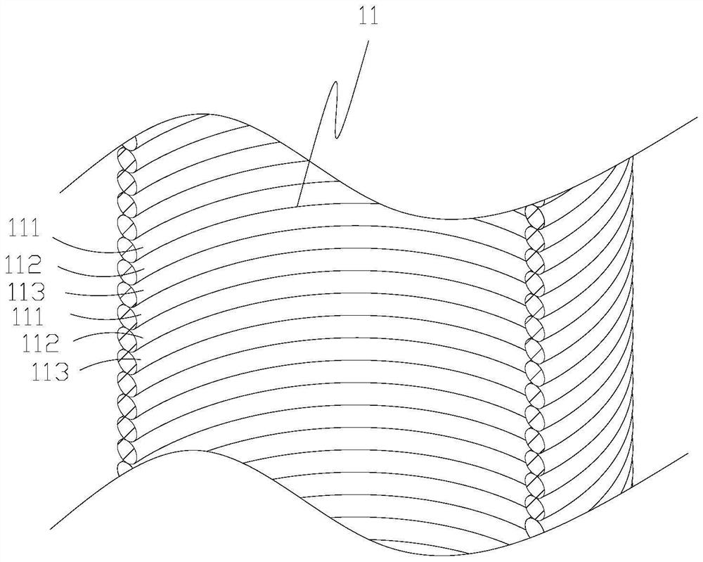
[0048]Specifically, the connecting wire 1 includes an inner connecting layer 11, an inner insulating layer 12, an outer connecting layer 13, and an outer insulating layer 14. Both the inner connecting layer and the outer connecting layer are made of conductive materials, and the specific types of materials are not limited. It is enough to meet the medical standard; both the inner connection layer and the outer connection layer are formed by synchronous curling of multiple metal wires, which are opened in a spiral structure and have elasticity; in this embodiment, the outer connection layer 13 is composed of 4 metal wires (4 wires) ...

Embodiment 2

[0072] Such as Figure 18-20 As shown, the implant end also includes multiple sets of positioning structures provided at the end of the housing 20, and the positioning structures include a sliding groove 271, an auxiliary implant head 272, a radial hole 273, and a radial locking head 274 , limit lock head 275, limit hole 276; sliding groove 271 is provided with a plurality of, evenly opened at the end of the housing 20, and the side wall of the sliding groove 271 is provided with a relief groove along the radial direction of the housing 20, Through the side wall of the housing 20; the auxiliary implant head 272 can be slidably arranged in the sliding groove 271, and has a hollow cylindrical structure; two radial holes 273 are provided, and are opened in the longitudinal direction of the auxiliary implant head 272. On the auxiliary implant head 272, the opening is arranged radially along the housing 20; the radial locking head 274 is slidably arranged in the radial hole 273 on ...


PUM


Abstract

The present invention discloses an electrode wire. The electrode wire comprises a connecting wire and an implantation end; the implantation end comprises an implantation head capable of moving back and forth; and the implantation head penetrates into body tissue in a puncture mode. A mode that the implantation head penetrates through the body tissue is set to be a puncture mode, so that the implantation head can break through the endocardium very easily, implantation of the implantation head is more convenient and labor-saving, and selection of pace-making sites is more diversified.

Description

technical field [0001] The invention belongs to the technical field of artificial cardiac pacemakers, and in particular relates to an electrode lead. Background technique [0002] Cardiac pacemaker is an electronic therapy device implanted in the body. It sends out electric pulses powered by batteries through the pulse generator, and through the conduction of the wire electrodes, it stimulates the myocardium in contact with the electrodes, so that the myocardium is excited and contracted, so as to achieve therapeutic effect. For the purpose of cardiac dysfunction due to certain arrhythmias and heart failure. [0003] One end of the existing electrode wire implanted in the body tissue is made into a helical shape, so that the implanted end can break through the endocardium and reach the pacing site through the helical screwing method; however, due to the closer the bundle of His in the ventricle The closer the area is to the physiological pacing site, but the closer to the H...

Claims


Application Information

Patent Timeline
Patent Type & Authority Applications(China)
IPC IPC(8): A61N1/05A61N1/372
CPCA61N1/0587A61N1/372
Inventor 江隆福
Owner MEI HOSPITAL UNIV OF CHINESE ACAD OF SCI
Why Eureka
Try Eureka