
Ultra-high molecular weight polyethylene pipe forming system and process

An ultra-high molecular weight, polyethylene pipe technology, used in tubular articles, applications, household appliances, etc., can solve the problem that the material in the forming area is not full enough, the quality of pipe forming is reduced, and the forming gap between the forming sleeve and the forming mandrel cannot be completely filled. and other problems to achieve the effect of ensuring the quality of processing

Active Publication Date: 2021-02-19
东营市东达机械制造有限责任公司
View PDF38 Cites 1 Cited by
  • Summary
  • Abstract
  • Description
  • Claims
  • Application Information

AI Technical Summary

Problems solved by technology

[0005] The purpose of the present invention is to provide a UHMWPE pipe molding system and molding process, to solve the above-mentioned background technology. In the actual transportation process, it is easy to cause the cavity to be unable to be filled due to the agglomeration of raw materials, resulting in a large space between the conveyed materials, resulting in insufficient material conveyed to the forming area, and resulting in a forming gap between the sizing sleeve and the sizing mandrel. Can not be fully filled, resulting in defects in the pipe forming body, thereby reducing the quality of the pipe forming
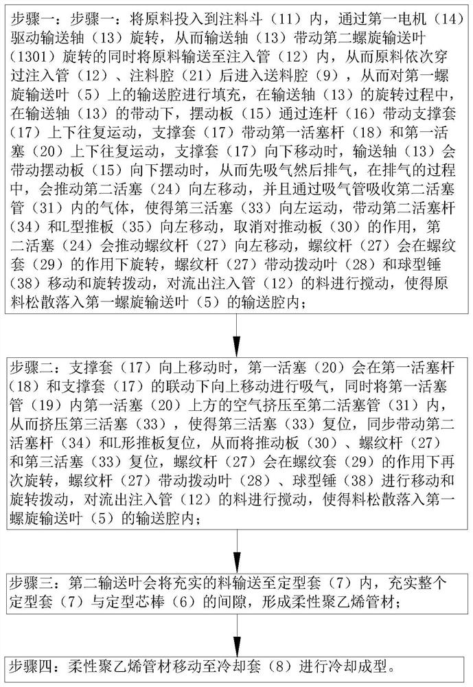
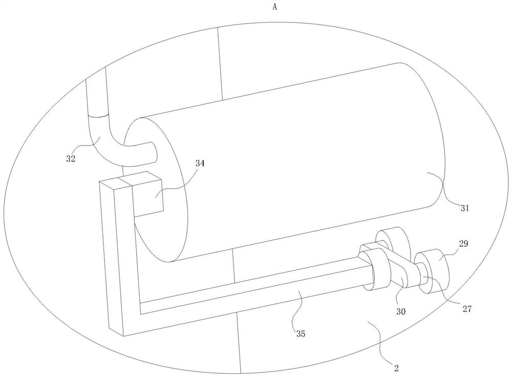
[0008] When working, in the prior art, during the process of screw conveying and forming the forming raw materials of pipes, the conveying cavity on the spiral blade is likely to be unable to fill the cavity due to the agglomeration of raw materials during the actual transportation process, resulting in a large gap between the conveyed materials. Due to the large space, the material transported to the forming area is not sufficient, and the forming gap between the shaping sleeve and the shaping mandrel cannot be completely filled, resulting in defects in the formed body of the pipe fittings, thereby reducing the quality of the pipe fittings. This technical solution solves the problem. The above problems, the specific working principle is as follows, the raw materials are put into the injection hopper, and the first motor drives the conveying shaft to rotate, so that the conveying shaft drives the second screw conveying blade to rotate and at the same time conveys the raw materials into the injection pipe, so that the raw materials pass through the injection pipe in turn. After the pipe and the injection chamber enter the feeding chamber, the conveying chamber on the first screw conveying leaf is filled. During the rotation of the conveying shaft, the swing plate drives the support sleeve to reciprocate up and down through the connecting rod, and the support sleeve drives the first piston. The rod and the first piston reciprocate up and down. When the support sleeve moves down, the conveying shaft will drive the swing plate to swing down, so that it first inhales and then exhausts. During the exhaust process, it will push the second piston to move to the left. , and absorb the gas in the second piston tube through the suction pipe, so that the third piston moves to the left, driving the second piston rod and the L-shaped push plate to move to the left, canceling the effect on the push plate, and the second piston will push the threaded rod Moving to the left, the threaded rod will rotate under the action of the threaded sleeve, and the threaded rod will drive the moving blade to move and rotate to stir the material flowing out of the injection pipe, so that the raw material will loosely fall into the conveying chamber of the first screw conveying leaf , when the first piston moves to not seal the gas injection pipe, the gas that continues to be discharged will be injected into the annular nozzle, and the gas vibration will be performed on the material accumulated below, so that the material can be fully filled in the conveying cavity of the first screw conveying leaf; the support sleeve When moving upward, the first piston will move upward under the linkage of the first piston rod and the support sleeve to inhale air, and at the same time squeeze the air above the first piston in the first piston tube into the second piston tube, thereby squeezing the third piston tube. The piston makes the third piston reset, synchronously drives the second piston rod and the L-shaped push plate to reset, thereby resets the push plate, threaded rod and the third piston, the threaded rod will rotate again under the action of the threaded sleeve, and the threaded rod drives the dial The movable blade moves and rotates to stir the material flowing out of the injection pipe, so that the material falls loosely into the conveying cavity of the first screw conveying leaf; The gap between the entire shaping sleeve and the shaping mandrel forms a flexible polyethylene pipe, and the flexible polyethylene pipe moves to the cooling jacket for cooling and forming; during the rotation of the conveying shaft in the present invention, the swing plate drives the supporting sleeve to reciprocate up and down through the connecting rod, The support sleeve drives the first piston rod and the first piston to reciprocate up and down. When the support sleeve moves downward, the conveying shaft will drive the swing plate to swing downward, so that air is first inhaled and then exhausted. During the sequence of inhalation and exhaust , the second piston will drive the threaded rod to reset and move to the left and then to the right, the threaded rod will rotate under the action of the threaded sleeve, and the threaded rod will drive the moving blade to move and rotate to stir the material flowing out of the injection pipe. Make the material loosely fall into the conveying cavity of the first screw conveying blade, and in the process of exhausting, when the first piston moves to not seal the gas injection pipe, the gas that continues to be discharged will be injected into the annular nozzle, and the accumulation below The material is subjected to gas vibration to make the material as full as possible in the conveying cavity of the first screw conveying leaf, and the second conveying leaf will convey the sufficient material to the shaping sleeve to fill the gap between the entire shaping sleeve and the shaping mandrel to ensure the shape of the formed pipe. Processing quality

Method used


Image

  • Ultra-high molecular weight polyethylene pipe forming system and process
  • Ultra-high molecular weight polyethylene pipe forming system and process
  • Ultra-high molecular weight polyethylene pipe forming system and process

Examples


Embodiment Construction

[0038] The following will clearly and completely describe the technical solutions in the embodiments of the present invention with reference to the accompanying drawings in the embodiments of the present invention. Obviously, the described embodiments are only some, not all, embodiments of the present invention. Based on the embodiments of the present invention, all other embodiments obtained by persons of ordinary skill in the art without creative efforts fall within the protection scope of the present invention.

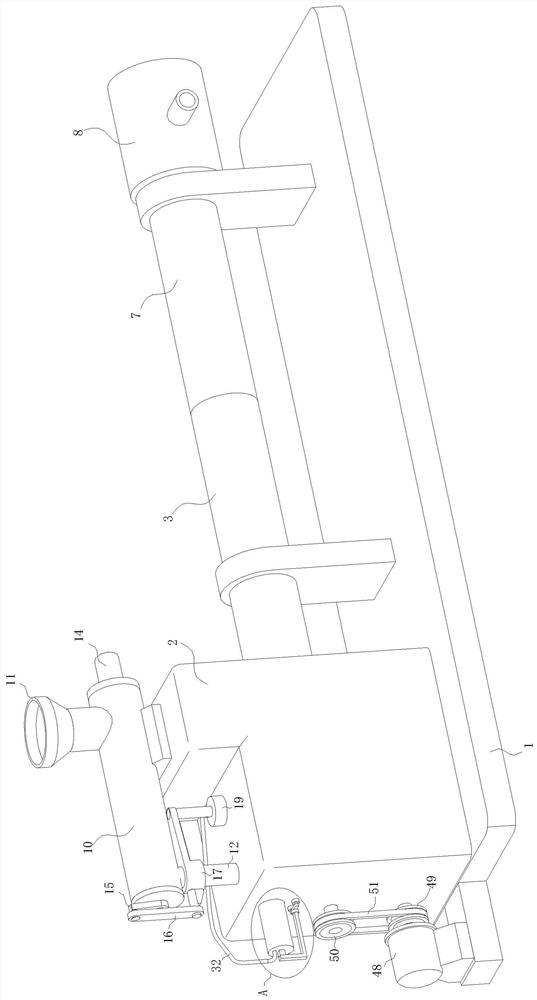
[0039] see Figure 1-13 , the present invention provides a technical solution: an ultra-high molecular weight polyethylene pipe forming system, including a base 1, a hopper seat 2, a barrel 3, a feeding shaft 4, a shaping mandrel 6, a shaping sleeve 7 and a cooling jacket 8, and a hopper The seat 2 is fixedly connected to the left side of the top of the base 1, the inside of the hopper seat 2 is provided with a feeding chamber 9, the barrel 3 is fixedly connected t...


PUM


Abstract

The invention discloses an ultra-high molecular weight polyethylene pipe forming system and process, and belongs to the technical field of ultra-high molecular weight polyethylene pipe forming. The ultra-high molecular weight polyethylene pipe forming system comprises a base, a hopper base, a machine barrel, a feeding shaft, a shaping core rod, a shaping sleeve and a cooling sleeve, the hopper base is fixedly connected to the left side of the top of the base, and a feeding cavity is formed in the hopper base. The machine barrel fixedly communicates with the right side of the hopper base and communicates with the feeding cavity. According to the ultra-high molecular weight polyethylene pipe forming system and process, materials flowing out of an injection pipe are stirred, so that the materials loosen and fall into a conveying cavity of a first spiral conveying blade, in the exhaust process, when a first piston moves to not seal an air injection pipe, continuously exhausted air can be injected into an annular spray head to vibrate the materials accumulated below, the conveying cavity of the first spiral conveying blade is filled with the materials as much as possible, a second spiral conveying blade can convey the filled materials into the shaping sleeve, a gap between the whole shaping sleeve and the shaping core rod is filled, and the machining quality of formed pipes is guaranteed.

Description

technical field [0001] The invention relates to the technical field of ultra-high molecular weight polyethylene pipe forming, in particular to an ultra-high molecular weight polyethylene pipe forming system and a forming process. Background technique [0002] The prior art discloses some invention patents for ultra-high molecular weight polyethylene pipe molding. The Chinese patent application number is 200710053227.2, which discloses a single-screw extrusion barrel molding method and molding method for ultra-high molecular weight polyethylene (UHMWPE) pipes. The equipment utilizes the extrudable and calendering properties of ultra-high molecular weight polyethylene in a high elastic state. When the ultra-high molecular weight polyethylene in a high elastic state is under the action of a certain extrusion force, it is filled with When the cavity is formed, the preliminary molding of the ultra-high molecular weight polyethylene pipe is realized. Under the continuous action of...

Claims


Application Information

Patent Timeline
IPC IPC(8): B29C48/10B29C48/285B29L23/00B29K23/00
CPCB29C48/10B29C48/285B29C48/022B29L2023/005B29K2023/06
Inventor 贾小军
Owner 东营市东达机械制造有限责任公司
Learn More