Biological fermentation tank

A bio-fermentation tank and drive shaft technology, applied in bioreactor/fermenter combination, specific-purpose bioreactor/fermenter, biomass post-treatment, etc., can solve the problem of unfavorable biological rapid fermentation and increase the risk of biological fermentation , unfavorable biological reproduction and fermentation and other issues

Inactive Publication Date: 2021-02-19
向桂秀
View PDF2 Cites 0 Cited by
  • Summary
  • Abstract
  • Description
  • Claims
  • Application Information

AI Technical Summary

Problems solved by technology

[0007] Aiming at the deficiencies of the prior art, the present invention provides a biological fermentation tank, which solves the problem that the traditional biological fermentation tank releases pressure only when the air pressure increases to a certain extent, and the fermented product that has been fermented and expanded is easily discharged together when the pressure is released. Causes waste of re...

Method used


Image

  • Biological fermentation tank
  • Biological fermentation tank
  • Biological fermentation tank

Examples


Embodiment 1

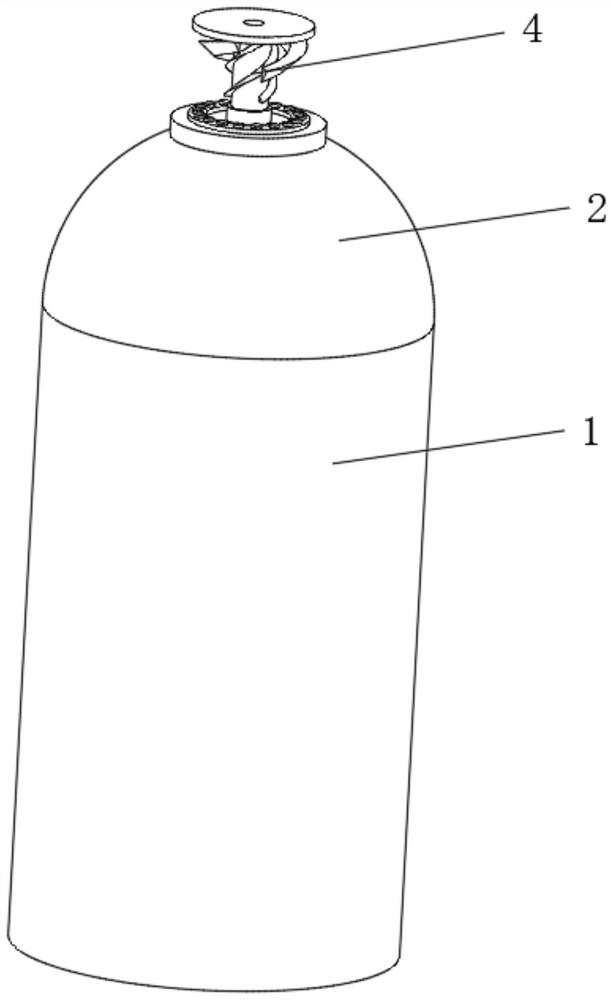
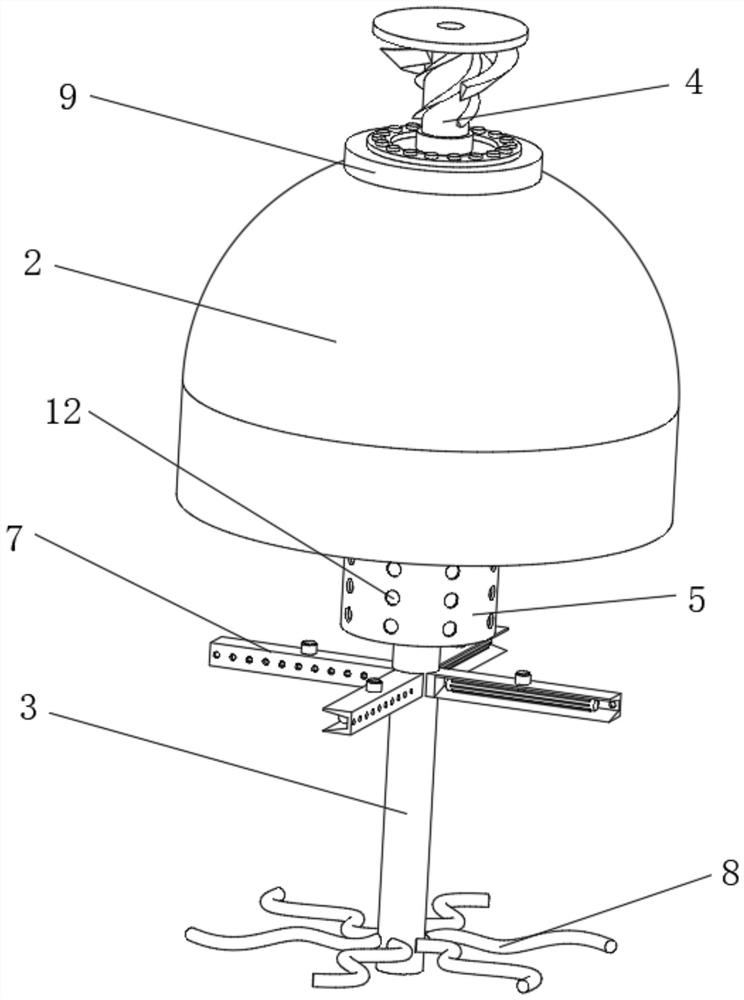
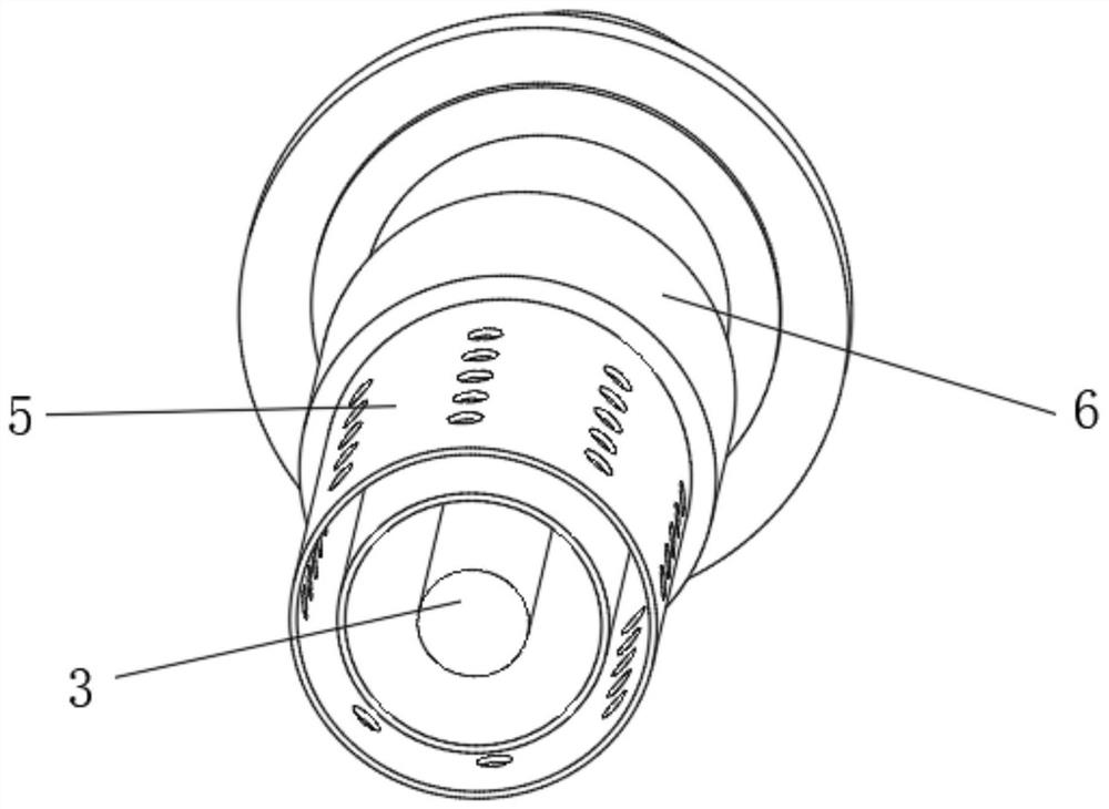
[0037] Such as Figure 1-5 As shown, the present invention provides a technical solution: a biological fermentation tank, including a fermentation inner tank 1, the top of the fermentation inner tank 1 is fixedly connected with a processing top tank 2, and the top of the processing top tank 2 is fixedly connected with an inlet sealing plate 9 , the top inside the processing top groove 2 is rotatably connected with a drive shaft 3, and one end of the drive shaft 3 extending to the top of the processing top groove 2 is fixedly connected with an exhaust drive mechanism 4, and the top of the processing top groove 2 is located outside the drive shaft 3 The quantitative discharge frame 6 is fixedly connected to the position of the quantitative discharge frame 6, and the bottom of the quantitative discharge frame 6 is fixedly connected with the defoaming outer frame 5. And the position below the defoaming outer frame 5 is evenly and fixedly connected with a shoveling mechanism 7, and...

Embodiment 2

[0042] Such as Figure 6 As shown, on the basis of Embodiment 1, the present invention provides a technical solution: a biological fermenter, the exhaust drive mechanism 4 includes an auxiliary connecting shaft 401, and the bottom axis of the auxiliary connecting shaft 401 is connected to the drive shaft 3 Fixedly connected, the top of the auxiliary coupling shaft 401 is fixedly connected with a windshield backing plate 402 .

[0043] The outer surface of the auxiliary coupling shaft 401 is evenly and fixedly connected with a driving spiral piece 403 , and both sides of the bottom of the windshield backing plate 402 are fixedly connected with aerodynamic blades 404 . Realize the complete guidance of the pressure release to form a mechanical force to ensure that the fermentation liquid can be fully stirred.

[0044] The aerodynamic vane 404 is arranged outside the driving helical piece 403 , and the output direction of the aerodynamic vane 404 arranged outside the driving heli...

Embodiment 3

[0046] Such as Figure 7 As shown, on the basis of Embodiment 1 and Embodiment 2, the present invention provides a technical solution: a biological fermenter, the exhaust drive mechanism 4 includes an auxiliary coupling shaft 401, and the bottom axis of the auxiliary coupling shaft 401 is connected to the The driving shaft 3 is fixedly connected, and the top of the auxiliary shaft 401 is fixedly connected with a windshield backing plate 402 .

[0047] The outer surface of the auxiliary coupling shaft 401 is evenly and fixedly connected with a driving spiral piece 403 , and both sides of the bottom of the windshield backing plate 402 are fixedly connected with aerodynamic blades 404 . Realize the complete guidance of the pressure release to form a mechanical force to ensure that the fermentation liquid can be fully stirred.

[0048] The aerodynamic vane 404 is arranged outside the driving helical piece 403 , and the output direction of the aerodynamic vane 404 arranged outside...


PUM


Abstract

The invention discloses a biological fermentation tank. The biological fermentation tank comprises a fermentation inner tank, wherein a processing top groove is fixedly connected to a top of the fermentation inner tank, an exhaust driving mechanism is fixedly connected to an end, extending to a top of the processing top groove, of a driving shaft rod, a quantitative discharging frame is fixedly connected to a position, located on an outer side of the driving shaft rod, of the top of the processing top groove, a bottom of the quantitative discharging frame fixedly communicates with a defoamingouter frame, material blocking filter holes are evenly formed in an outer side surface, close to a lower portion, of the defoaming outer frame, shoveling mechanisms are evenly and fixedly connected topositions, located below the defoaming outer frame, of a surface of the driving shaft rod, stirring serpentine rods are evenly and fixedly connected to an outer side surface, close to a bottom end, of the driving shaft rod, and a pressure relief spray pipe is fixedly connected to a surface of a top of the driving shaft rod and located on an outer side of the exhaust driving mechanism. The invention relates to the technical field of biological fermentation. The biological fermentation tank achieves a purpose of realizing periodic quantitative pressure relief of a fermentation tank and avoidingtraditional one-time pressure relief to cause a large amount of fermented products to be discharged together.

Description

technical field [0001] The invention relates to the technical field of biological fermentation, in particular to a biological fermentation tank. Background technique [0002] Biological fermentation engineering is an important part of biological engineering. Microorganisms use carbohydrates to ferment to produce various industrial solvents and chemical raw materials. Ethanol, acetone-butanol, butanol-isopropanol, acetone-ethanol, 2,3-butanediol, and glycerol fermentations are some of the forms of solvent fermentation performed by microorganisms. [0003] For example, the Chinese invention publication number is: CN102206578B, a biological fermentation defoaming device, including a fermenter and a stirring shaft, a static cylinder with a static cavity is fixed on the inner top wall of the fermenter, and the side wall of the static cylinder is There is an exhaust pipe communicating with the static chamber of the stationary cylinder, the lower end of the stirring shaft passes t...

Claims


Application Information

Patent Timeline
IPC IPC(8): C12M1/02C12M1/12C12M1/21C12M1/00
CPCC12M27/02C12M29/04C12M41/02C12M45/02
Inventor 向桂秀
Owner 向桂秀
Why Eureka
Try Eureka