
Drive circuit for single-phase direct-current brushless sensorless motor

A DC brushless, drive circuit technology, applied in the direction of AC motor control, single motor speed/torque control, electric components, etc., can solve the problems of not being able to know the current position of the rotor, many power devices in series, and low driving efficiency. Achieve the effect of simple and reliable hardware circuit, easy integration and improved reliability

Pending Publication Date: 2021-02-19
陈波 +1
View PDF6 Cites 0 Cited by
  • Summary
  • Abstract
  • Description
  • Claims
  • Application Information

AI Technical Summary

Problems solved by technology

[0005] 1) The current motor uses a Hall sensor switch to generate a signal at the moment when the rotor magnetic pole is switched, so as to know the current position of the rotor. The conventional Hall sensor switch can only generate a signal at the moment when the rotor magnetic pole is switched. During the rotor transfer process The current position of the rotor cannot be known, so it can only be driven by a square wave, the driving efficiency is low, the torque fluctuation is large, and the electromagnetic noise is large during operation;
[0006] 2) Due to the use of Hall sensors for position sensing, the drive circuit that provides the drive current is powered by a single-cell lithium battery and needs a booster circuit to reduce the drive current, resulting in a complex drive circuit and many power devices in series in the coil drive current path. Low circuit efficiency, high cost, and reduced reliability

Method used

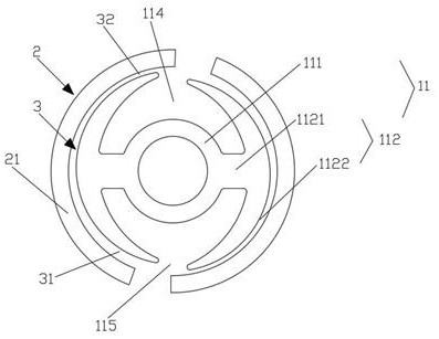
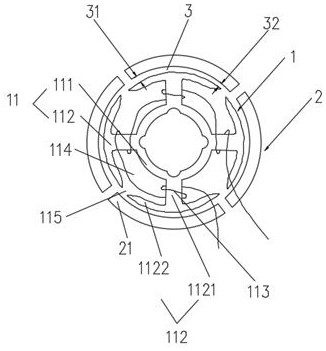
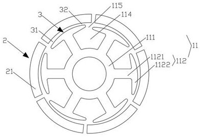

Image

  • Drive circuit for single-phase direct-current brushless sensorless motor
  • Drive circuit for single-phase direct-current brushless sensorless motor
  • Drive circuit for single-phase direct-current brushless sensorless motor

Examples


Embodiment Construction

[0039] Example embodiments will now be described more fully with reference to the accompanying drawings. Example embodiments may, however, be embodied in many forms and should not be construed as limited to the examples set forth herein; rather, these embodiments are provided so that this disclosure will be thorough and complete and fully convey the concept of example embodiments to those skilled in the art.

[0040]Furthermore, the described features, structures, or characteristics may be combined in any suitable manner in one or more embodiments. In the following description, numerous specific details are provided in order to give a thorough understanding of embodiments of the invention. However, those skilled in the art will appreciate that the technical solutions of the present invention may be practiced without one or more of the specific details, or other methods, components, means, steps, etc. may be employed. In other instances, well-known methods, apparatus, impleme...


PUM


Abstract

The invention discloses a drive circuit for a single-phase direct-current brushless sensorless motor, and the drive circuit comprises a main drive circuit which comprises a single-chip microcomputer U2, field-effect transistors Q2-Q5, and a resistor R6 which is used for collecting a current value in a stator coil (113) in a rotating process of a rotor (2). According to the drive circuit provided by the invention, the current value in the current coil is obtained through the current sampling resistor R6 single-chip microcomputer, the current has a function relationship with the position and therotating speed of the brushless motor rotor, and the current rotor position can be calculated through the current. The motor adopts a position-sensorless mode, the work of a driving circuit is not influenced by motor vibration and temperature rise, and the reliability of the motor is improved.

Description

technical field [0001] The invention relates to the field of electronic circuits, in particular to a driving circuit for a single-phase DC brushless motor without a position sensor. Background technique [0002] Single-phase DC brushless motor is driven by only a single phase current in the excitation coil, and the rotor part is composed of permanent magnets or excitation coils with paired magnetic poles. The motor back EMF is a single phase AC voltage. The drive current commutation is completed by an external circuit, and the commutation time point is provided by an external Hall position sensor. [0003] Single-phase DC brushless motor is driven by only a single phase current in the excitation coil, and the rotor part is composed of permanent magnets or excitation coils with paired magnetic poles. The motor back EMF is a single phase AC voltage. The drive current commutation is completed by an external circuit, and the commutation time point is provided by an external H...

Claims


Application Information

Patent Timeline
Patent Type & Authority Applications(China)
IPC IPC(8): H02P6/08H02P6/10H02P6/18H02P25/16H02P25/022
CPCH02P6/085H02P6/10H02P6/18H02P25/16H02P25/022H02K2201/03
Inventor 陈波何义松
Owner 陈波
Learn More