Camera pose estimation method
A pose estimation and camera technology, applied in computing, navigation computing tools, image data processing, etc., can solve the problem of low design accuracy of robot speed odometry, and achieve the goal of improving design accuracy, shortening matching time, and improving estimation accuracy. Effect
- Summary
- Abstract
- Description
- Claims
- Application Information
AI Technical Summary
Problems solved by technology
Method used
Image
Examples
Embodiment 1
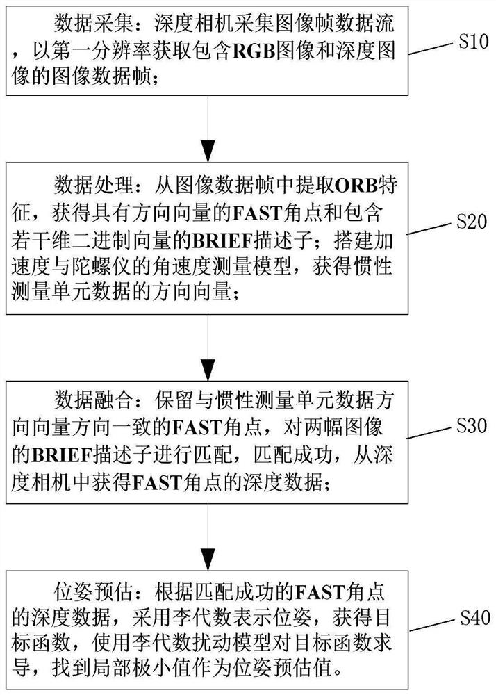
[0057] Such as Picture 1-1 As shown, the present invention provides a camera pose estimation method, which is used in the technical field of robot navigation and positioning. The camera pose estimation method includes the following steps, as shown in Figure 1:
[0058] S10. Data collection: the depth camera collects the image frame data stream, and obtains the image data frame including the RGB image and the depth image at the first resolution;
[0059] S20. Data processing: extract ORB features from the image data frame, obtain FAST corner points with direction vectors and BRIEF descriptors containing several-dimensional binary vectors; build angular velocity measurement models for acceleration and gyroscopes, and obtain the direction of inertial measurement unit data vector;
[0060] S30. Data fusion: keep the FAST corner points consistent with the IMU data direction vector direction, match the BRIEF descriptors of the two images, and if the matching is successful, obtain ...
Embodiment 2
[0083] On the basis of Embodiment 1, the embodiment of the present invention mainly describes the acquisition of FAST corner points. Get a FAST corner point with a direction vector like Figure 3-1 shown, including the following steps:
[0084] S21. Downsampling once: the image data frame of the first resolution is subjected to a downsampling process to obtain the image data frame of the second resolution;
[0085] S22. Extracting FAST corner points: by comparing pixel brightness, extracting FAST corner points from the image data frame of the second resolution, adding feature point arrays;
[0086] S23. Obtain the direction vector of the FAST corner point: determine whether the acquired FAST corner point is in the feature point array: if yes, retain the feature value of the FAST corner point, rotate the FAST corner point to obtain its direction vector; if not, Delete the eigenvalues of the FAST corner;
[0087] S24. secondary downsampling: carry out secondary downsampling...
Embodiment 3
[0090] On the basis of Embodiment 2, the embodiment of the present invention mainly provides an example of extracting FAST corner points in step S22. Such as Figure 3-2 As shown, the extraction of FAST corner points includes the following steps:
[0091] From the image data frame of second resolution, extracting brightness is the target pixel of Ai, and setting brightness threshold is T;
[0092] Taking the target pixel as the origin, take several pixels on a radius circle and number them clockwise;
[0093] Detect the brightness of several clockwise pixel points to determine whether the target pixel is a FAST corner point: if the brightness of 3 or more pixels is greater than Ai+T or greater than Ai-T at the same time, and the brightness of 12 consecutive pixels is greater than Ai+ at the same time T or less than Ai-T, then determine the target pixel as a FAST corner point and add it to the feature point array;
[0094] If it is not satisfied that the brightness of three ...
PUM
 Abstract
Description
Claims
Application Information
 - R&D
- Intellectual Property
- Life Sciences
- Materials
- Tech Scout
- Unparalleled Data Quality
- Higher Quality Content
- 60% Fewer Hallucinations
Browse by: Latest US Patents, China's latest patents, Technical Efficacy Thesaurus, Application Domain, Technology Topic, Popular Technical Reports.
© 2025 PatSnap. All rights reserved.Legal|Privacy policy|Modern Slavery Act Transparency Statement|Sitemap|About US| Contact US: help@patsnap.com


