Two-pole permanent magnet solid rotor motor inductance design method based on flux linkage integration method
A technology of solid rotor and integral method, which is applied in electromechanical devices, manufacturing motor generators, design optimization/simulation, etc., can solve problems such as not being universal, not applicable, multi-computer hardware resources and time, etc. Adaptability requirements, the effect of meeting the rapidity requirements
- Summary
- Abstract
- Description
- Claims
- Application Information
AI Technical Summary
Problems solved by technology
Method used
Image

Examples
Embodiment Construction
[0031] In order to make the purpose, technical solutions and advantages of the present invention clearer, the present invention will be further described in detail below in conjunction with the examples and accompanying drawings. As a limitation of the present invention.
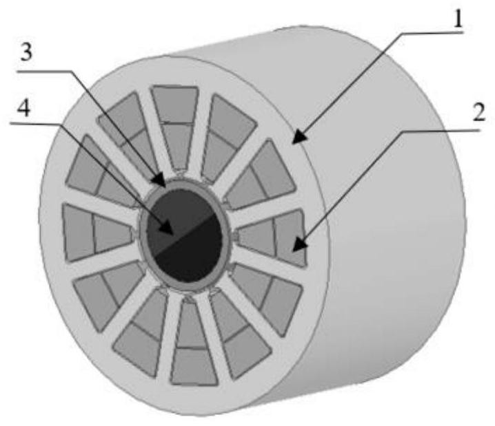
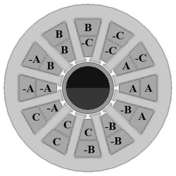
[0032] see figure 1 , the present invention relates to a two-pole permanent magnet solid rotor high-speed permanent magnet motor stator core 1 and stator winding 2, and a rotor sheath 3 and rotor magnetic steel 4. The whole system adopts 2 poles and 12 slots, and the stator winding adopts double-layer short-distance distribution Arrangement, the stator winding is divided into three phases, and the division of phase belts can be found in figure 2 , along the counterclockwise direction are +A, -C, +B, -A, +C, -B.
[0033] The two-pole permanent magnet solid rotor high-speed motor inductance design method based on the flux linkage integral method of the present invention comprises the following steps:
[00...
PUM
 Abstract
Description
Claims
Application Information