Narrow-linewidth external cavity laser and optical module
A laser, narrow linewidth technology, applied in the field of optical communication, can solve problems such as small volume, achieve the effect of small volume, narrow linewidth, and reduce the number of components
- Summary
- Abstract
- Description
- Claims
- Application Information
AI Technical Summary
Problems solved by technology
Method used
Image
Examples
Embodiment 1
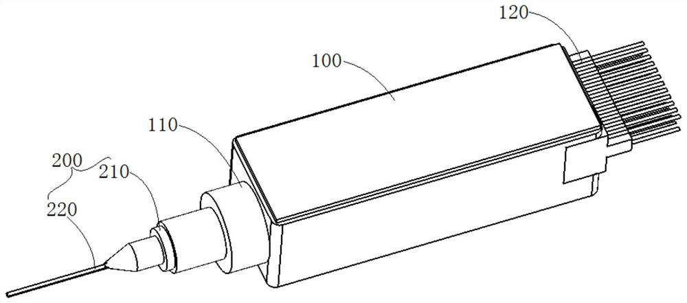
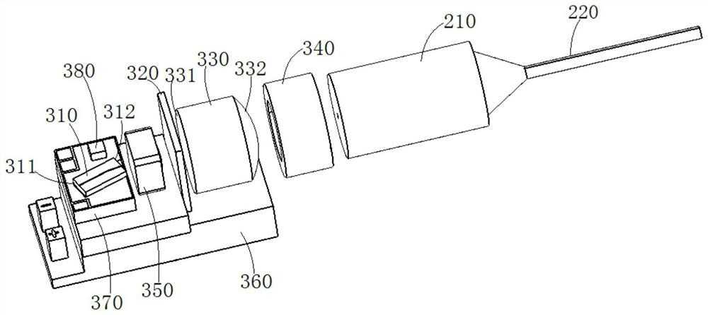
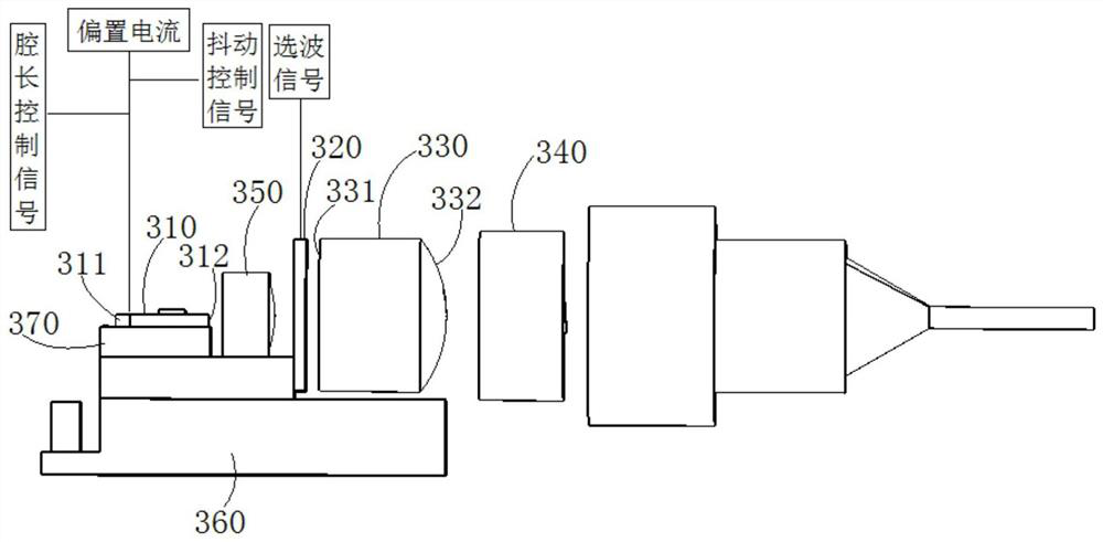
[0046] Such as Figure 1-3As shown, the laser assembly disposed in the sealed housing 100 includes an external resonant cavity, a gain chip 310 and a tunable wavelength selection element 320 disposed in the external resonant cavity, and the sealed housing 100 is also provided with a coupling lens 330 and The isolator 340 is connected with the optical fiber 200 to the optical interface 110 of the sealed housing 100 , and the laser output from the laser assembly is coupled into the optical fiber 200 through the coupling lens 330 , and then transmitted to the outside of the housing 100 through the optical fiber 200 . The above-mentioned optical fiber 200 includes an optical fiber head 210 and a pigtail. Wherein, the optical fiber head 210 includes a fixed sleeve, such as a glass sleeve, in which a capillary is disposed, and one end of the pigtail is disposed in the capillary; the fixed sleeve of the optical fiber head 210 is disposed in the optical interface 110 of the housing 10...
Embodiment 2
[0053] Such as Figure 5 As shown, different from Embodiment 1, the above-mentioned laser assembly further includes an actuator 390, a cavity surface of the external resonant cavity is arranged on the actuator 390, and the above-mentioned jitter control signal is applied to the actuator 390, By adjusting the actuator 390 to shake the cavity surface of the external resonant cavity on it, the output optical signal is shaken, so as to lock the central wavelength of the output light beam. Here, the actuator may be a piezoelectric element, an acousto-optic element, an electro-optic element, a liquid crystal component, MEMS or other linear motors, and the like.
[0054] In this embodiment, the positions of the isolator 340 and the coupling lens 330 are different from those in Embodiment 1, the positions of the isolator 340 and the coupling lens 330 are exchanged, the isolator 340 is arranged behind the wavelength selection element 320, and the coupling lens 330 is integrated in a se...
Embodiment 3
[0059] Such as Figure 7 As shown, the difference from Embodiment 2 is that in this embodiment, there is no actuator in the laser assembly, but a cavity length jitter element 390a is set in the external resonant cavity, and the cavity surface of the external resonant cavity can be set on the isolator 340, or on the fourth plane 391a of the cavity-length dithering element 390a away from the wavelength selection element 320. The isolator 340 and the coupling lens 330 are arranged behind the output cavity surface of the external resonant cavity. In this embodiment, the output cavity surface of the external resonant cavity is arranged on the fourth plane 391a away from the wavelength selection element 320 of the cavity length dithering element 390a, and the isolator 340 and the coupling lens 330 are arranged behind the cavity length dithering element 390 . The jitter control signal is applied to the cavity length jitter element 390a. By controlling the cavity length jitter element...
PUM
 Abstract
Description
Claims
Application Information
 - R&D
- Intellectual Property
- Life Sciences
- Materials
- Tech Scout
- Unparalleled Data Quality
- Higher Quality Content
- 60% Fewer Hallucinations
Browse by: Latest US Patents, China's latest patents, Technical Efficacy Thesaurus, Application Domain, Technology Topic, Popular Technical Reports.
© 2025 PatSnap. All rights reserved.Legal|Privacy policy|Modern Slavery Act Transparency Statement|Sitemap|About US| Contact US: help@patsnap.com


